wiring problem with npn

Luc De Ridder

Member
Join Date
Mar 2003
Location
Aalst
Posts
4
we use an embedded plc controller that is configured as npn. We have the following problem now. When we do not put power on the plc (24V) but we put power on the outputs (coming from the contcators and so on) the plc is powering up by himselves and is putting some outputs high. This is normal as tough the output connections is flowing 24V+ to the Inputs (0V). The question now is, how we can avoid this? By putting optocouplers between every output and the physical element it has to switch? or does somebody have some other idea?
 
Last edited:
power on computer

In normal plc the outputs are isolated from the running computer and thus no problem.
In your case i am suspecting a diode is in to prevent high voltage on the transistors.
so if you put 24 volts on the output line it will go back into the powerline via this diode.
I hope you can find this line coming from the outputs and going to the power connector.
just open this line and connect it to your external 24 volt line.
if needed more info just send message to [email protected]
 
Confused

we use an embedded plc controller that is configured as npn.

If I have misunderstood please explain. I am not sure whether you are wiring incorrectly or stating that power is flowing thru devices and feeding the 24v via the common point.

Are the outputs also npn?

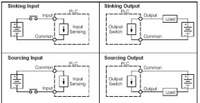
If so then why are you putting power to the plc outputs? Using the following picture as an example if the controller is configured for npn then the inputs and outputs would be sinking therefore the plc commons would be attached to the negative (-) of the 24vdc supply.

Sinking = Path to supply ground (–)
Sourcing = Path to supply source (+)

iowiring.jpg
 
Received via Private Message

Thanks for your quick reply. The problem we have is I think quite normal.
Let's explain step by step:

We do not put 24V to the powersupply of the plc. But this transfo that normally forseen for the powersupply to the plc, we use also to feed the loads and the sensors.
The loads (relais, contactors and so on are connected to the +24V)
The inputs (sensors) are connected to the 0 volt.
So, when we put the powersupply on (plc power not connected), there is a flow of cuurent from the +24V from the loads to the 0V of the inputs. This seems to be ok to power up the plc, without putting the plc to the powersupply.
As this can be a very dangerous situation, we need to avoid this. The question is how?
Note that the plc is npn for in and outputs. All sensors are npn as well as the loads.
If you have any solution for this, please advise.

Best Regards,
Luc De Ridder

You never mentioned what brand of controller so its hard to give a definitive answer. My first thought would be to use a relay on the power source to the plc to feed the power to the I/O...ie whe the plc is powered the relay will be turned on allowing power for the I/O. Considering this may be a safety issue I am not sure I would trust that method.

I dont understand how the controller could be powered by the inputs...that does not make sense. I would think the device is faulty if it can be powered thru sensors etc.
 
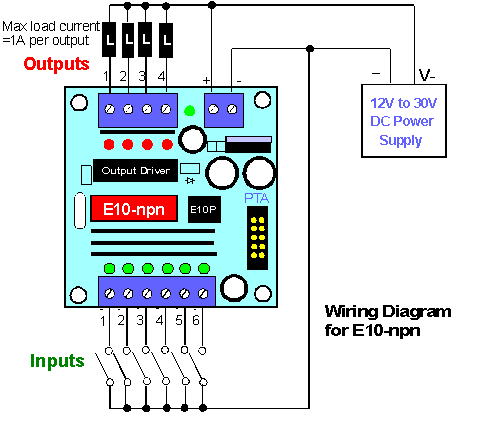
You didnt state what model is was but are you wiring it like this? Is the power supply being used a good industrial grade? No fluctuating voltage?

figb2.gif


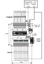
or this:

t22hnpn.jpg
 
Model: T100MD1616

After looking at the installation manual: http://www.tri-plc.com/inst-md.pdf I have a couple of questions.
1. Is the device set for 24vdc? No jumper for 12v operation?
2. Are you using the same power for I/O as you are for the plc, if so why are the inputs being powered when the plc is not? Leakage can always be an issue with transistor outputs, depending on device you may need to use opto-isolators.

Om page 3 of that manual it suggests using a capacitor and diode on the power supply side to filter transients etc...I think I would do that.

Last but not least....is the plc actually powering up and outputs actually turning on? LED's and/or devices?
OR
Are you just measuring the voltage at those points with a digital multimeter? That will happen because transistors "leak" and digital multimeters are sensitive enough to measure that leakage current.
 
We like to keep the questions and answers on the forum

yes, I use the same powersupply. I was thinking to put optocouplers in the output lines to avoid this problem. What do you think? And/or also the inputs??
We measure the voltage and an engine is working (while the fuses of the pwerline to the plc are disconnected!!!!

It would help if more details were provided all at once. You stated an engine is running...is that a motor? Are you using PWM to drive a servo or stepper? OR is a contactor/relay coming on turning on a single or 3 phase motor?

The installation manual I gave the link for gives examples and reasons for using opto-isolation.

I still think there must be a problem with the plc and/or the wiring. Is it possible you attempted to drive a load/motor that needed more current then the outputs are rated for? In that case an output may be "shorted" and allow a device to operate. Remove power from all of it and do a continuity check between the outputs and common to see if one or more is shorted...ie allow a path for power all the time.
 
Thanks for the link to the manual Ron! Very helpful!.. :cool:

I think Shooter and Ron are on the right track with the backfeed idea. Since the PLC power supply and the I/O commons seem to be connected internally, this is a likely situation. If the load is a coil, +24V will be seen at the output, and transistor outputs will allow this to also be seen at the common (AKA, the OV terminal).

Is the power supply floating or grounded? If grounded, which side is grounded (+24V or 0V)? There is no separate ground terminal on the PLC. Is it grounded via it's mounting screws, or is 0V (or +24V) considered 'ground'? Although it's marked +24V and 0V, the PLC may not be polarity sensitive... (n)

I question why the outputs are powered before the PLC. Normally, the PLC should always has power so it is 'aware' of what's going on. I hate finding a PLC that's wired to lose power when E-Stops are pressed. Just bad practice IMO... (n)

I always use one PLC output to 'enable' the control/safety circuit. Note that this is NOT using the PLC as the safety circuit, but simply adding the PLC output (via a N.O. relay) into the hardwired safety circuit. Think of this output as just an 'additional' E-stop switch. This prevents starting of the machine unless the PLC is 'alive and well', with the added benefit of being able to 'E-stop' the machine from logic... (y)

One more 'safety' issue I'll mention. The commons for 'critical' outputs should receive power through the MCR, so they can't be turned on 'accidentally' by the PLC... 👨🏻‍🏫

Time to break out the meter and start troubleshooting!... :D

beerchug

-Eric
 
Perhaps Luc does not know how to 'reply' to a thread? Got this via PM...

Hi Eric, thanks for the reply.
The problem is that we discovered it because we did not wire thi electrical box ourselves. They are putting fuses in the powerline to the plc, so, when we tested the electrical box step by step, we putted first electricity to the loads (contactors, etc) and the inputs.
As in the plc was an old program, it was seting the corresponding output on.
We also put the +24V to the earth(we have to do so here in Belgium) and the 0 volt is not on earth.
So, to eliminate this unsafe situation, we have to take a way the fuses in the line to power up the plc and than we put first the plc on and when this is ok, we give power to the loads and so on.
But than I suppose we need to use two separete powersupplies, one for the plc and one for the loads and inputs and we use an output to give power to the loads and inputs after the plc was doing the self-check.
Is there no danger than that we have interferences from the powersupply for the loads and inputs to the plc?
When we push an Estop, we keep the plc running.
Best Regards,
Luc
I think you'll have the same problem even if you use a separate power supply for the outputs, as this PLC 'shares' the 0V connection... :rolleyes:

You can isolate where the problem lies with a simple test. Remove the wire from the +24V terminal on the PLC, tape it off, then power up the outputs. Does the PLC power up anyway? If so, then you have to figure out where the PLC is getting the +24V power from. If it does NOT power up, then you must have +24V on that wire you removed, which is wrong. You'll have to trace where that wire goes to find out how it is getting the +24V... :unsure:

Keep us posted on your progress so we can help you figure this one out!... :cool:

Use the
reply.gif
at the top or bottom of this page so everyone can help.

beerchug

-Eric
 

Similar Topics

This is my first post so I am new to this website. Well to start with I have set card dipswitch to external power supply. I am feeding 24vdc to...
Replies
28
Views
6,960
What we have is a three phase motor with six wires and no idea how it was wound , not low voltage or high. My question is that we know the wires...
Replies
21
Views
6,720
Dear All i am using a siemens 6ES7331-1KF01-0AB0 card as ana anlog input my sensor uses seperate power supply so i have 2 wires with +,- 24...
Replies
3
Views
8,904
Posted this to Reddit with little success, so I figured I would share it here as well. Very new to PLCs, but figured I would give it a shot to...
Replies
0
Views
122
Hello Folks, Has anyone configured a Momentum high speed counter on Unity 13.1. We need the wiring diagram for Momentum High speed counter and...
Replies
0
Views
76
Back
Top Bottom