Total beginner

Nhrafan26

Member
Join Date
Nov 2008
Location
Slatington, PA
Posts
53
Ok, I am trying to learn PLC programming and have a PLC already with a copy of WinGPC that I'm playing around with.
I have read through material on this site a few others here and there.
I was able to connect a circuit and write a simple little program to take input from a switch then activate 4 outputs after a timer of 200ms, then turn off each light sequentially at 8 sec, 6sec, 2sec then the last one.
I'm trying to think of things to write a program for and thought of the garage door opener.
I'm kind of stuck on the light circuit though...
How would you write a program to turn on the light when the door opens or closes then stay on for a period of inactivity until automatically turning off?
This sounded like a simple thing until I go to write it...
Thanks.
 
assuming that you just want a hint and not a giveaway:

if the PLC you're working with has a TOF (Timer Off Delay) instruction, try programming the motor to control the TOF ... then use the TOF Done bit or the Timer Timing bit (if you have one) to control the lamp ... then maybe reverse an "open" contact to a "closed" contact, or vise-versa, etc. ...

play around with those ideas and see what you come up with ...
 
Last edited:
Ok, I was able to connect to the motor output and have the light stay on for XX seconds after motor activates.
Now, anyone know how to make a one shot button in WinGPC?
How to program to use the same button to start and stop process?
Or how to make an input reset after using once? Like a garage door opener button?
I did read about MC and Master reset (?) but don't really understand it yet. Would I use this for something like that?
I know when looking around at programs at work in AB I see bits labeled one shot but don't know how to put that in WinGPC.
 
Now I'm really getting beside myself here...
I have a handful of Cutler-Hammer E65-SMPR3-GD P.E.'s and cannot get them hooked up any way to trigger an input on the plc.
I am hooking the black wire to the input terminal of plc, the brown wire to the com of input card and the blue wire to 120V. Am I doing something wrong here or what?
It says on back of p.e. it's a 3M Polarized reflex 16-264VAC, 18-50VDC 200mA Series A1
Showing that brn (L1) hooks to -
Bk hooks to V+ through Load
BU (L2) hooks to V+
Anyone help me out here?
Thanks.
 
Nhrafan26 said:
Now I'm really getting beside myself here...
I have a handful of Cutler-Hammer E65-SMPR3-GD P.E.'s and cannot get them hooked up any way to trigger an input on the plc.
I am hooking the black wire to the input terminal of plc, the brown wire to the com of input card and the blue wire to 120V. Am I doing something wrong here or what?
It says on back of p.e. it's a 3M Polarized reflex 16-264VAC, 18-50VDC 200mA Series A1
Showing that brn (L1) hooks to -
Bk hooks to V+ through Load
BU (L2) hooks to V+
Anyone help me out here?
Thanks.

Nhrafan26,

First a couple of questions.

1. Are the inputs to the PLC AC or DC? If they are DC are they sinking or sourcing?
2. The Photo eye has indicator lights on it do they light up and change state.
3. This appears to be a retroreflective sensor. I do not see any mention of a reflector in your post.
4. Reading between the lines in your post Im guessing you do not have the "com of the input card" as you called it referenced to neutral. Before you do this make sure the input card is for 120V AC.

This photo eye appears to be a "fits all photo eye" meaning it will work in any application AC or DC. Normally in a AC application the brown wire would be connected to 120V hot, the blue wire connected to the neutral and the com of the input also connected to neutral, and finally the black wire connected to the respective input.
 
Nhrafan26 said:
when looking around at programs at work in AB I see bits labeled one shot but don't know how to put that in WinGPC.

I'm not familliar with WinGPC, but there is a way to roll your own oneshot on any PLC, even modicon if you are carefull with placement.
rollyourownoneshot.jpg

.
I do not know what letters WinGPC uses for inputs, outputs and internal bits. You will have to make adjustments accordingly.
 
Thanks for the program example, I will have to try entering something like that when I get a chance to get back to it. (working a lot the next few days)

Now, as for the sensor...
I do have a reflector and all that to make it work. The lights do light up on the top of the sensor and change states when the beam is broken.
The input card on the PLC is an AC input card.
The COM term. is connected to neutral of AC line.

I will try connecting how you said, again, when I get a chance to look at in on Wed. morning.

I had it connected opposite of how you said in your post so I will have to see what happens when I do it the other way.

Thank you.
 
OK, tried the one-shot thing and it isn't working like I want it to.
Is there any way to have the same switch be the on AND off button?
Like you start the input with a switch, then use the same switch and input to stop the input?? I think I said that right...

I have a limit switch that I want to turn on a rung, then run through the scan, then turn off the rung the next time it is made regardless of how many scans take place.
Is this possible?
I'm probably getting more complicated than I should already but it's just one thing that's bugging me.
 
Nhrafan26 said:
OK, tried the one-shot thing and it isn't working like I want it to.
Is there any way to have the same switch be the on AND off button?

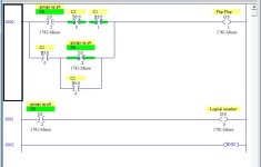
Ahh!!! You want a Flip Flop!

flipflopanyplc2.jpg


You may notice it has some of the same parts. X100 is an input C1 and C2 are internal bits. Although you could use outputs in their place. It is also possible to use a counter to do what you want to do. Just have it reset itself when the count becomes higher than 1 if you want a two position flip flop. From here I think you can figure out what is needed if you wanted a 3 0r 4 position flip flop or "ratchet".

Glad to hear your photo eye works!
 
Awesome!
That worked perfectly!
Exactly what I was looking for.

Thank you for the help!

I'll play around with this stuff for a while and I'm sure I'll be back to ask plenty of questions in short time.

One question I did have is tonight I was looking in some programs and saw a "watchdog fault" (Believe that's what it's called) in AB RSLogix 5000.
What is this?
 
A watchdog is usually referring to a toggling status bit that is used to monitor communications. Device A generates the pulsing signal and Device B checks to ensure that it does not stop pulsing. If it does then the rest of the communications is suspect.


Brian.
 
Ahh!!! You want a Flip Flop!

flipflopanyplc2.jpg


You may notice it has some of the same parts. X100 is an input C1 and C2 are internal bits. Although you could use outputs in their place. It is also possible to use a counter to do what you want to do. Just have it reset itself when the count becomes higher than 1 if you want a two position flip flop. From here I think you can figure out what is needed if you wanted a 3 0r 4 position flip flop or "ratchet".

Glad to hear your photo eye works!

Where is the "One Shot" in this diagram ?

Why doesn't mine work ?

Oneshot10.jpg
 
1. Outputs should be addressed as B3 not O to match the contacts in the logic.
2.If you need real world physical outputs, add the O outputs as parallel branches.
 
Last edited:

Similar Topics

So I hope I've stumbled upon a good source of help. I read the FAQ's but didn't see anything pertaining to specifically what type of material is...
Replies
34
Views
8,749
Hello With my background in programming and web development a friend came to me for help building a SCADA system, but I'm a newcomer to HMIs...
Replies
3
Views
1,511
I'm being tasked with supporting / upgrading these panels but no software, cable, documentation. I have an old laptop running XP and would like...
Replies
4
Views
1,994
Hi everyone, I'm trying to perform a serial download with a Total Control Quickpanel jr (QPK-2xxxx) using an old computer running QuickDesigner...
Replies
3
Views
1,671
Back
Top Bottom