Siemens 313C-2DP Address allocation

saleshark

Member
Join Date
Oct 2008
Location
nantwich
Posts
19
Hi All

I am currently working on a project using the CPU above. I haven't worked with Step 7 before so I'm working it out as I go on.

I have configured the HW with the following components.

313C-2DP using the following via profibus
Accopus Drive x 4
Wago Distributed I/O x 5

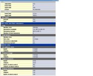
This has automatically assigned the following addreses.

Each Accopus drive requires 32 bytes input and 32 bytes output, I will only use the first 4 bytes of both though.

Step 7 has assigned the following

Accopus Drive 1 - Byte 2-33
Accopus Drive 2 - Byte 34-65
Accopus Drive 3 - Byte 66-97
Accopus Drive 4 - Byte 128-159

Now when I click on each of the drives in HW config I can open them up and see the individual I/O Bits on the first three drives as they are listed as Bool. My question is that the 4 drive is only listed in Bytes. Can I still address individual Bits on a Byte on this drive, if so how do I address them.

I hope you can understand the question and also have an answer.

Steve
 
The 313C can only address 128 bytes in the PIQ memory area. Your 4th drive is in the peripheral area and can only(*) be addressed as a byte/word/dword using Load and transfer instructions to PIW/PQW128+

(*) edit: SFC14/15 can also be used

313009.jpg
 
Last edited:
Hi Steve.

I would change the suggested address.

It is most likely that the drives require all 32 bytes to be transferred in one big chunk from the PLC program, this is called "data consistency".
Notice that i/o bytes 0-127 are within the normal proces image of the CPU, and these are automatically transferred consistently.
For drive 1, the assigned addresses are all within the proces image. But drives 2-4 have assigned some of the addresses within the proces image, and some outside the proces image. This could lead to problems.
Also, bytes 0-1 are probably used in your system to some normal i/o, so you have exhausted all the process image of the CPU.

It would be more "normal" to assign the drives adresses that are outside the proces image. From byte 128 and onwards.
You then define a common DB to store the data that is used by the drive.
Next, you use the system blocks SFC14 and SFC15 to transfer the data to/from the i/o adresses consistently.
In this way you keep the normal proces image i/o adresses free to use with regular i/o.

To sum it up:
i/o bytes 0-127 are typically used by digital (boolean) i/o. You can access the adress in the PLC program without having to worry about data consistency.
i/o bytes 128 - .. are typically used for analog i/o and drives.
Analog i/o typically use one word, and you can use L PIWxx and T PQWxx to transfer the data.
Drives and other complex devices that require data consistency over more than 4 bytes, require that you use DPRD_DAT/DPWR_DAT SFC14/SFC15 (for an onboard DP port) or DP_SEND/DP_RECV FC1/FC2 (for a DP port in a CP module).

edited: I wrote that there are 256 bytes in the proces image which is wrong. LD got it right.

Thanks Jesper

It's a bit beyond me at the moment, The drives use their own windows based software as they are pick and place units.

The 32 byte telegram is used as follows.

Bytes 0 - 3 are control bits on either the digital input or digital output. These I can configure myself in the windows software.

These are the bits I need to interface with, could you give me an example of how I would do this in step 7?

The other bytes are below but I won't need to use these as I can set a sequence in this software and just activate it in the first four bytes, Also I am only using Y and Z axis.

Byte 4 & 5 are reserved

Byte 6 & 7 are Alarms

Byte 8 - 11 are alarm additional information

Byte 12 - 15 Current X axis

Byte 16 - 19 Current Y Axis

Byte 20 - 23 Current Z Axis

Byte 24 - 27 Current A Axis

Byte 28 - 31 Spare
 
Hi again Steve.

First, I still recommend that you move the addresses to outside the proces image.

It doesnt matter if you dont use all of the assigned addresses. You probably have to transfer all 32 bytes consistently. It is not difficult, just look up the help for SFC14 and SFC15.
To find out if consistency is required or not, you go to STEP7 HW Configuration and open the properties of the i/o data for the drive(s).
Check the property "Consistent Over". If it says "Total Length" you must use SFC14/SFC15. If it says "Unit" you can just use normal L PIWx, L PIDx (load) and T PQWx, T PQDx (transfer).

With SFC14/SFC15 you define a DB as an intermediary storage for all the data that is sent to and from the drive.

In case consistency is not necessary, you can transfer up to 4 bytes with L and T :
L PID128 will load bytes PIB128..PIB131.
T PQD128 will transfer bytes PQB128..PQB131.

To access individual bits, you can write
A PI128.0
= PQ128.0

But it is better to do
L PID128 // get inputs from drive
T MD100 // store in merker address
A M100.0 // load bits
= "drive_running"
A M100.7 // load bits
= "error_is_active"
...
A "start_command"
= M104.0
L MD104
T PQD128 // transfer outputs to drive

(the above is just an example. I dont know what functions each individual bit has for your drive).

Hi Jesper

Thank you for your reply, I now have my machine in a position to try programming the drive.

Could you give me a code for the following please.

I wish to initiate a sequence on my drive. I have moved all four drives out of the process image as you suggested. And I don't need consistency over the telegram length.

The first four input and output bytes of the telegram are the ones I set in the drives software.

So First I need to enable the drive.

This is address I128.1

I then need to assign my sequence no. 1

This is address I129.0

and then intiate the sequence

This is address I128.5

I'm really struggling to get this drive running in auto.

Any help would be appretiated
 

Similar Topics

Hi every body, i am goning to change cpu313c 2dp instead of cpu 314. Is it possible? What shuld i do? Please help. Regards
Replies
3
Views
2,798
Hello there! Is there anyone else who has ever had all the CPU's LEDs flashing at the same time?! I can't seem to find anything about this in...
Replies
3
Views
1,714
hello Friend There is one old system with S7 300 CPU which is password protected and I dont know the password. Now I want to remove the password...
Replies
6
Views
5,917
Hello everybody i have a siemens cpu 313c and when i tern power on all leds at front of cpu stay for a sort time on and after all leds go off...
Replies
3
Views
2,658
Hello; I need help downloading a program to a Siemens CPU 313C. The program was uploaded from a 314IFM. I modified the HW Configuration by...
Replies
10
Views
13,660
Back
Top Bottom