timbo_uk
Member
Hi,
After dropping onto Ken Roach's excelent info (MR PLC Forum in November 2007; Google is great!)on using EII rather than HSC, I need a little help with an output not operating as expected.
I have 2 flowmeters to use on a project I am (still) developing, only 1 works at a time so I was initially going to use a relay to select either signal to an input to the HSC.
The pulse train is about 1mS on 4mS off.
After reading Kens post I decided to try using EII. So I can have independant inputs to the PLC; therefore less to go wrong in future!
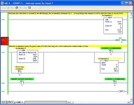
To test on the bench I have copied Kens ladder and added a little for my test routine (as attached image). The ladder routine called at each rising edge on I:0/0.
This counts as expected, but I wanted to check to make sure it hit all pulses, and didnt miss any. So I added O:0/2 at rung 1, expecting it to pulse each time the interupt section was called. I was then going to put a 2 channel scope on I:0/1 and O:0/2 and check for a match at varying frequencies.
Some how this output just stays on all the time.
What stupid thing am I missing please?

Last edited:


