1794-IE-4X0E2 Analog Combo PLC5 problem

p_logix

Member
Join Date
Aug 2008
Location
winnetka
Posts
52
Hi Im Having a problem setting up a flex 1794-IE-4X0E2 Analog Combo card on a PLC5. Both of my input devices to my combo card are working fine. One of the inputs are a Feedback loop from a actuator 4-20 ma, and a temperature transmitter 4-20 ma. When I have 20 ma I read 30840 on my BTW,BTR configuration. The problem I have is My 2 Channel Outputs are not working. When My PID is at 100% I am only sending 4095 which is equal to 6.125 ma. Now I know on the older PLC 1771 analog cards 4095 is equal to 20 ma 12 bit resolution. I've tried changing my PID Output Limit High to 753.112, and my analog output sends 30840 which is 20 ma. However if my setpoint changes on my PID with the output high limit set to 753.112, the setpoint has no effect and 30840 stays on my output. I have seen some controllogix PLCs use a mov instruction and send the value into a binary word in order to get the output to work. I hope someone has set up a flex analog output module and can tell me how It sends 30840 which is equal to 20 ma, what am I missing? All my configuration bits are correctly set right for 4-20 ma. My BTW/BTR is working correctly.

Thanks
 
For the most helpful help.
Post your .RSP file ( zip it first) and someone can take a look.

It sounds like all you need to do is rescale the PID output from 0-4095 to 0-30840. You can use a compute instruction to do this.
i.e ( PID Output * 7.53) = Scaled Output ( for analog card)
( N7:0 * 7.53) = N7:1 Your registers will be different of-course.
But again to be sure post the program.
Oh and change that Output Limit High back to 100.
 
Last edited:
Status

Setpoint 2200 PID initialized Yes
Process variable 11 A/M Station Mode Auto
error 2189 Status Enable(EN) 1
Output % 753.112 proportional gain (KC) 0.15
mode Auto Reset Time (TI)(Mins/Repeat):0.06
PV alarm High Derivative rate (TD) (mins) 0
Deviation Alarm Positive Deadband 0
Output limiting High Output Bias % 0
SP out of Range No Tieback % 0
Error within deadband No Set output % 753.112

Configure

PID Equation Dependent Input Range Maximum 30840
Derivitive of PV Input Range minimum 0
Control action SP-PV Output limit High % 753.112
PV tracking No Output limit Low % 0
Derivative Smoothing No PV alarm high 0
Zero Crossing Deadband No PV alarm Low 0
Bias Back Calculation No PV alarm Deadband 0
Update Time secs 0.25 (+) Deviation alarm 0
Cascaded Loop no (-) Deviation alarm 0
Cascaded type N/A Deviation alarm Deadband 10
Master to this Slave PD N/A
Engineering Unit Maximum 30840
Engineering Unit minimum 0

Ok if I set my Output limit high to 100% I only get 6.125 ma out even when My PID says the output is a 100%. I don't have the RSP. at the moment, but when I get it I'll post. Thanks again.

One more thing if I do a compute ( PID Output * 7.53) = Scaled Output ( for analog card) Do I make my Control variable the integer value and take value and MOV it In to My BTR/BTW N29:20? For my output?
Thanks.

PID

Control Block PD22:7
Process Variable N29:2
Tieback 0
Control Variable N29:20 (This is writing to my output)
 
Last edited:
One more thing if I do a compute ( PID Output * 7.53) = Scaled Output ( for analog card) Do I make my Control variable the integer value and take value and MOV it In to My BTR/BTW N29:20? For my output?
Thanks.

PID

Control Block PD22:7
Process Variable N29:2
Tieback 0
Control Variable N29:20 (This is writing to my output)

Yes, the destination of of the compute ( or multiply ) instruction can point to the BTR/BTW register for the analog output. Or use a MOV for that, your choice.
You will have to change the "Control Variable" register in your PID instruction. Can't have them both pointing to your BTR/BTW register.
 
Last edited:
Ok if I set my Output limit high to 100% I only get 6.125 ma out even when My PID says the output is a 100%. I don't have the RSP. at the moment, but when I get it I'll post. Thanks again.

The reason your output is 6.125 ma is at 100% output the value of register N29:20 is 4095. At this value ((4095/30840)*16ma)+4ma=6.125ma
This is why you need to rescale the output( of your PID) to 0-30840 before it is moved to the analog card BTR/BTW register.
 
Last edited:
Thanks Mickey,

It works however I found another way to do it in the manual.

Using a compute
CPT
compute
Dest N7:49
Expression ((362.4 + 14.4)!30840.0)*N29.2)*10.0

PID

Control Block PD22:7
Process Variable N7:49
Tieback 0
Control Variable N7:29

If we do it this way it will be more accurate because we are scalling the range of are actual pressure transmitter 362.4, 14.4. But we will have to do a lot of changes to our HMI programming Intellution IFix Program.

HMMMM? I'm glad you got it working, but I fail to see what that
compute instruction and its dest ( N7:49) has anything to do with the PID output scaling. What ever works.
 
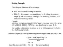
Here is the example from the AB manual on the bottom I finally dug it out, The N7:49 is just a place holder we created to see if it worked, and also made it the process variable for a test and it worked also. But like I said If we do it this way we have to reprogram alot of stuff. Thanks again,

scale.jpg
 

Similar Topics

Hey Everyone, After reading a lot on this forum and elsewhere I see not many are fond of the 1794-VHSC module. I can see to a degree as I was...
Replies
3
Views
154
I'm sure this question has been posted a thousand times on here but for me it was even funnier when I got to ask Rockwell / AB directly. My...
Replies
5
Views
164
Hello, a customer i support has DH+ RIO racks all over the plant. they use 1794-asb modules. today they had a rack fault out and go unresponsive...
Replies
0
Views
647
I have to configure new 1794-ADN Series C in my devicenet network. I have downloaded the EDS File and registered it. But while configuration in...
Replies
3
Views
1,042
Hi Newbie here :yeah: Can one of you experts help me with setting up a simple BTR and BTW to just test 4 analogue inputs 4-20ma (1974-if4i)...
Replies
11
Views
997
Back
Top Bottom