Communication CPU315-2DP and SIMOREG66A70 via Profibus

gumis

Member
Join Date
Mar 2009
Location
Bialystok
Posts
30
Hi

My purpose is to establish communication between CPU315-2DP and SIMOREG6RA70. I am going to use SFC14 and SFC15 functions to send information by PPO3. I have the following question:

Do the PZD1 become one of sixteen words and their corresponding connectors ( K3001-K3016) automatically after end of transmission or I have to carry out some operation? If the second,please tell me where can I find suitable information.
 
PPO3 specifies two words of PZD Data. It is normal to send the control word as PZD1 and Speed setpoint as PZD2. You are correct in assuming that they will become K3001 and K3002.

Items you need to setup include: P654 On/Off1 B3100, P655 Off2 (coast stop) B3101, P658 Off3 (Quick stop) B3102, P665 fault reset B3107, P443 Main Setpoint K3002.

Nick
 
Dear Nick,

Thanks a lot.

Where did you find the information that PZD1 becomes K3001?

I am going to use SFC14 and SFC15 to transfer data from/to PLC. Also, I have to specify the PPO type in PLC. If I will choose for instance,PPO1, will the PKE go to K3001?

Regards,
gumis
 
Last edited:
My purpose is to drive a motor on the constant speed. Could you help me with the following problems:

1. What does 'inching' mean? Should I enable this function?

2. What is happening with the drive if I enable ' Fast stop ' function?

3. I have read description of Ramp-function generator but I still do not understand what I will get on the output of r-f generator when I apply sine wave for instance.
 
Last edited:
I'm out the office today so have limited time online.

Inching means to run the drive slowly at a fixed speed.

If Fast Stop becomes false then the drive will ramp to a stop in the shortest time possible and then switch off.

The GSD file for a CBP2 should be available in the hardware config in Step7.

If you only need to run the drive at a fixed speed then set the speed setpoint to one of fixed setpoints pre-programmed in the drive (Sorry no manual and can't remember the tag numbers Have a look at the parameter list in drive monitor).

Nick
 
Thanks a lot.

My idea is to send double word by SFC15 to the drive. I suppose less significant 16 bits will be Control Word 1 submitted on G180 and more significant 16 bits will be Main Setpoint. I want to use Move instruction in PLC to write constant value determined by these 32 bits and then send it by SFC15. Is it a right idea? I can use fixed setpoint pre-programmed but this project is just for learning.

1. Could you tell me how the bit7 in Control Word 1 works? Is it a request of response from drive about actual speed,for instance?
2. I do not know why I cannot set parameters of the drive like rated armature current or rated armature voltage when I make start-up process. I have no idea.
 
Control word 1 bit 7 is the fault acknowledge; It operates on the rising edge of any bit set in P665, P666 or P667. If the drive is in a fault state that triggering this bit will clear the error and the drive will be ready for operation again.

Have a read of the section in the manual on startup (Chapter 7) this should guide you through commissioning the drive.

For data transfer, I recommend sending/receiving data from/to a data block where you can clearly define each bit in the control word etc. Better still, use UDTs. for example:

DB10.DBX0.0 = Word1 Bit 8
...
...
DB10.DBX0.1 = Word1 Bit 15
DB10.DBX1.0 = Word1 Bit 0 (OFF1)
DB10.DBX1.1 = Word1 Bit 1 (OFF2)
DB10.DBX1.2 = Word1 Bit 2 (OFF3)
...
...
...
DB10.DBX1.7 = Word1 Bit 7 (Fault Reset)

DB10.DBW2 = Speed Setpoint

You get the idea - I hope,

Nick
 
Thanks a lot,Nick.

I cannot use MasterDrive and Simatic till Tuesday,next week but I am trying to specify what to do.

I do not know if there is some difference between DB1 and DB10. In DB1 there are five columns: address, name, type, initial value, comment. The addresses are assigned automatically for succesive names of parameters. The only idea I understand is place RECORD in the column 'name' and initial value will be 32-words determined by control word 1 and status word.

Probably I did not understand your idea. Maybe it will change when I will be working on software for this project.
 
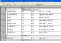
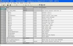
Attached are some pictures of UDTs performing similar functions to those proposed and a STL source file which contains UDT40, UDT41 and DB40; these can be imported to your project and compiled to produce the blocks.

Nick

FetchUDT.jpg SendUDT.jpg
 

Attachments

  • DriveData.zip
    1 KB · Views: 47
Thanks.

I can not see the program in STL till Tuesday,next week.

I have got the questions:

1. Where do you define the values of bits of word which you send?
2. In Simatic Manages the UDTs is one type of blocks among OB and DB. Am I right? I have not got Simatic right now so that's difficult.
 
The STL Source code is a text file which you can import into your project.

Your PLC program must control the values of the bits to be sent.

UDT is "User Defined Type", it acts like a "wrapper" for a collection of data, keeping it all together and making it easy to refer to in your program. When you come to using SFC 14/15 for the data transfer you'll be glad that the data is contained in a UDT as it makes thinks easier.

I'm out of the office now until next week.

Nick
 
I will investigate this program today.

Do you think it is proper idea to write to M memory 32-bit constant ( 16 less significant bits will be Control Word 1 and remaining 16 will be Main Setpoint - PZD2). Then, assign this memory space to RECORD parameter in SFC15. These bits will be also kept in UDTs.

I would like to ask you about SFC15. RECORD is the value to be sent from PLC memory to the drive. It can have more than two words. LADDR is some value from the drive which is written to PLC. Am I right? If yes, where will be source of this value ( LADDR) in the drive?
 

Similar Topics

I want to realize the communication S7 and pc by cable profibus or mpi I want to know the steps to that allows me to do it
Replies
0
Views
1,264
Hi folks, I could really use some help - I am trying to connect CP340 with my PC by RS232 protocol. I need to send some characters to PC from...
Replies
0
Views
1,897
hello i have a cpu315-2ag10-0ab0 can i connect 5 pg and 4 plc to industial ethernet . the 6 pg can't connect to cpu 315 caused to small resource...
Replies
0
Views
1,436
i have two plc 1. s7-1212dc/dc/dc ip; 192.168.0.1 2. s7-1500 1513-1pn ip; 192.168.3.2 i need to get data from plc1 to plc2. any idea how to do...
Replies
5
Views
45
I have created a project in TIA Portal v16 Upd6 with S7-1200 (6ES7214-1AG40-0XB0) and WinCC Unified (PC station). The communication between the...
Replies
4
Views
140
Back
Top Bottom