Low pass digital filter not working as expected

matt_sd

Member
Join Date
Jan 2007
Location
Australia
Posts
96
Hello all,

I have got a motion signal rate signal (in degrees per second) coming from a motion sensor via RS232 into my control system.

The signal has quite a lot of noise when the sensor has no motion but this noise is approx 50Hz. This application will be for the marine industry so I will only be interested in below 5Hz as the boat will not be able to move at a higher frequency above this.
Therefore I should be able to use a low pass filter to filter this noise. When the sensor is not moved, I should have 0 degrees per second on the rate, when moved, only have the rate signal and not the noise. I will be happy :)

The controller is Beckhoff Twincat and I have got a digital filter supplement from Beckhoff.

I have set up the filter (input/output/order filter and cycle time). All I need now is the coefficients.

I found this site that you select the filter (i.e I have selected Butterworth, Low pass filter 3rd order with a cutoff frequency at 5Hz

http://www.dsptutor.freeuk.com/IIRFilterDesign/IIRFilterDesign.html

It generates the coefficients:-

Butterworth IIR filter

Filter type: LP
Passband: 0 - 5 Hz
Order: 3

Coefficients

a[0] = 7.540253E-9 b[0] = 1.0
a[1] = 2.2620759E-8 b[1] = -2.992146
a[2] = 2.2620759E-8 b[2] = 2.9843228
a[3] = 7.540253E-9 b[3] = -0.9921768


I have added these coefficients to my filter and done some testing.
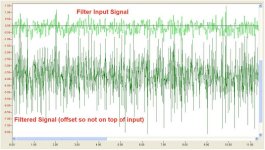
The filtered signal has more noise than the input signal where I would have expected the opposite and for this noise to be completely filtered out.

I have tried with different orders and also different cut off frequencies but cant filter this noise or even get a substantial reduction. I also set the cutoff frequency as 1Hz i.e. filter majority of the signal but there is still this high frequency noise.

I am quite new to filters, am I doing something wrong or missing something? Is there any other web site that generates these Coefficients so I can cross reference?


Any help/comments appreciated

Matt

PS
This is the details of he digital filter I am using:-
http://infosys.beckhoff.com/english...tml/tcplclibcontoller_ctrl_digital_filter.htm
low pass filter.jpg
 
Hello Peter,

there are above next to the a ones but quite close:-

a[0] = 7.540253E-9 b[0] = 1.0
a[1] = 2.2620759E-8 b[1] = -2.992146
a[2] = 2.2620759E-8 b[2] = 2.9843228
a[3] = 7.540253E-9 b[3] = -0.9921768
 
The transfer function is

y(n)=2.992146*y(n-1)-2.9843228*y(n-2)+0.9921768*y(n-3)+7.540253E-9*u(n)+2.2620759E-8*u(n-1)+2.2620759E-8*u(n-2)+7.540253E-9*u(n-3);

Did you remember to change the signs of the denominator? Notice that the sign of the coefficents in the denominator must be changed.
 
Hello Peter, the function does all the calculations .This function was created by Beckhoff and is in their library - it is locked so I cant see exactly what is occurring in the calculation but from their documentation:-
FB_Ctrl_DigitalFilter_G.gif


The function asks for the coefficients therefore the signs of the denominator will be as I type them in.


This was the example that came with the function block and the coefficients:-

(* set values in the local arrays *)
ar_CoefficientsArray_a[1] := 0.0; (* not used *)
ar_CoefficientsArray_a[2] := 0.2;
ar_CoefficientsArray_a[3] := 0.1;

ar_CoefficientsArray_b[1] := 0.6;
ar_CoefficientsArray_b[2] := 0.4;
ar_CoefficientsArray_b[3] := 0.2;

(This array in the function block starts from 1 rather than 0)

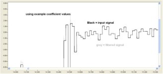
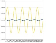
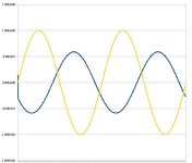
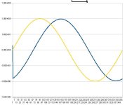
Using these default coefficients values, I do get a slight filtering: See graph, but these coefficients are just example ones.

By using the coefficients generated from http://www.dsptutor.freeuk.com/IIRFilterDesign/IIRFilterDesign.html
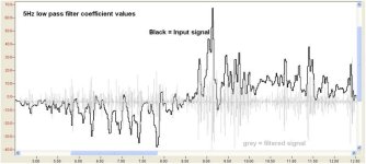
selecting 5Hz lowpass filter, if doesn't seem to filter and if the when the input signal rate changes is positive, the filter output seems to be both a positive and negative value and same when the input rate is a negative rate. (see graph below.)

Just can't explain it.

filter default values.jpg filter 5hz values.jpg
 
Is the Beckhoff computer using 32 or 64 bit math?

Look at the coefficients. You can add numbers that are 10^-9 to numbers that are in the range of 1 unless you are using 64 bit floats.

Try a second order filter. Usually filters do not have a higher order than two. If you want a 4 pole filter you cascade two two poles filters or biquads. What is the sample time of your filter? I assume you want a 5 Hz filter. I will be able to provide my solution tonight.

Try getting a first order filter to work. Perhaps there is something wrong with the way you are using the filter block or there is something wrong with the filter block itself. The filter block could be misleading in that it allows you to enter all the coefficients but it doesn't have the precision to do the math without a lot of rounding errors.

I could easily modify what I already have. I just need to know the sample rate and cutoff frequency.
ftp://ftp.deltacompsys.com/public/NG/Mathcad%20-%20Butterworth%20PLC.pdf
It would take me some time do a third order. A fourth order would we be faster as I have that done too.

One more thing. Since the coefficients in the numerator are small I am assuming you are sampling at a very high speed. Do you have a way of sampling at this speed without sample jitter? That will add noise too. That is why we sample using a FPGA instead of using interrupts.
 
First of all,
if you want cutoff frequency of 5 Hz, then at least, update time of your digital filter should be 10 Hz (or Ts = 0.1s).

Now, simple second order digital filter would look like this:
0.2929 z^2 + 0.5858 z + 0.2929
------------------------------
z^2 + 0.1716

This means:
b1 = 0.29229
b2 = 0.5858
b3 = 0.2929

a1 = 1;
a2 = 0;
a3 = 0.1716

Are you sure you're interpreting meanining coefficients in your documentation correctly?

Are you sure that if ar_CoefficientsArray_a[1] is not used, it's cvalue should be zero? Perhaps it should be 1.

Hope this helps.
 
Pandiani, that can't be right

All the coefficients must add up to 1. This is not counting the output term or leading z in the denominator which should be one.

Matt's B[1]+B[2]+B[3]+A[0]+A[1]+A[2]+A[3] add up to close 1. This is right, or almost right. Pandiani, your coefficients don't add up to one even close. See my pdf. I specifically check for this when doing calculations because it is an easy indication that I did something wrong. Also if the numbers add up close to 1, as in Matt's case, there may be rounding errors.

Usually the indexes represent time or sample delays. The current reading and output has an index of 0.

Usually A is used to represent the denominator and B the numerator.

Matt's numbers look like they should work but
1. We don't know what the sample time is and if it is the same as the sample time used to calcualate the coefficients.
2. We don't know how bad the sample jitter is.
3. We don't know what the float point precision is.
4. We don't know if the filter box works. It may be prone to round off error due to trying to implement the filter as one filter instead of a cascaded filter.
5. Matt needs to try a simple low pass filter. Then a second order Butterworth then a third. Matt can then be sure he is using the filter box correctly.
 
Matt - The coeficients you have obtained from the site mentioned are for a sampling rate of 8000 samples/sec - I'm guessing you are not actually sampling at that rate. If you are not, then all bets are off.

Here's a structered text block that implements a third order filter. It's written in Siemens SCL but will easily translate to the Beckhoff platform. You can but down the run time overhead by splitting out the coefficent calcs.

I've only tested the functionality using step changes so I haven't tested the frequency/phase response. Here's where I got the data from

http://www.apicsllc.com/apics/Sr_3/Sr_3.htm


Code:
FUNCTION_BLOCK FB9
VAR_INPUT
rCutOffFrequencyHz:REAL;
rSampleTimems:REAL;
rInput:REAL;
END_VAR
VAR_OUTPUT
rOutput:REAL;
END_VAR
VAR
  // 3rd order butterworth filter
rW:REAL;
rC:REAL;
rT:REAL;
rCSquared:REAL;  
rCcubed:REAL;
d:ARRAY[0..3] OF REAL;
n:ARRAY[0..3] OF REAL;
X:ARRAY[-3..0] OF REAL;
Y:ARRAY[-3..0] OF REAL;
END_VAR
rW:=rCutOffFrequencyHz * 2 * 3.1415927;
rT:=rSampleTimems/1000.0;
rC:= 1/TAN(rW * rT / 2.0);
rCSquared:=rC*rC;
rCCubed:=rCSquared*rC;
d[0]:= rcCubed + 2*rcSquared + 2*rc + 1.0;
d[1]:=-(3*rCcubed + 2*rCSquared - 2*rC - 3.0)/d[0];
d[2]:=(3*rCcubed - 2*rCSquared - 2*rC + 3.0)/d[0];
d[3]:= (-rCCubed + 2*rcSquared - 2*rC + 1)/d[0];
n[0]:=1.0/d[0];
n[1]:=3.0/d[0];
n[2]:=3.0/d[0];
n[3]:=1.0/d[0];
x[0]:= rInput;
y[0]:= n[0]*x[0] + 
       n[1]*x[-1] +
       n[2]*x[-2] + 
       n[3]*x[-3] - 
       d[1]*y[-1] - 
       d[2]*y[-2] - 
       d[3]*y[-3];
y[-3]:=y[-2];
y[-2]:=y[-1];
y[-1]:=y[0];
x[-3]:=x[-2];
x[-2]:=x[-1];
x[-1]:=x[0];
rOutput := y[0];
  ;
END_FUNCTION_BLOCK
 
All the coefficients must add up to 1. This is not counting the output term or leading z in the denominator which should be one.
Peter, I don't think that is necessarily true for Butterworth filters. This is of course true for FIR digital filters with windowing (sum of all coefficients is 1). I think that it is enough to check if gain is 1.
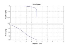
In my example gain is 1. Gain of my transfer function is 1. It is a second order Butterworth filter with cutoff frequency equal 5 Hz.
Please, have a look at the Bode plot in the attachment.

Bode.jpg
 
Simon, which software you used to obtain that graphs?
I stand corrected, filter:
simple second order digital filter would look like this:
0.2929 z^2 + 0.5858 z + 0.2929
------------------------------
z^2 + 0.1716

This means:
b1 = 0.29229
b2 = 0.5858
b3 = 0.2929

a1 = 1;
a2 = 0;
a3 = 0.1716
requires 20 Hz sampling rate and not 10 Hz.

Matt, can you provide us with feedback? Did you try this?
 
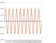
Using plcsim, I generated the sine waves using S7 plc code, fed it into the filter FB and then logged the input/output in two DB's from which I generated source code (text). I exported the source code then imported that into a spreadsheet (openoffice) and plotted the results.
 
Simon,
I don't want to hijack this thread, but can you please post some simple example about the way logging is done with PLCSIM?
Let's say, I have FB that is providing some output (or that can be for example PIWxxx). I assume you used two DBs, one for x (time) and one for y (actual) value. In this way it is possible to use DBs without need for static arrays, right? I think that some code would genereate new address to store value in each cycle. Problem is how to dynamically generate DB's addresses like DB1.DBWx?
Can you post some quick example?

Thank you very much
 
Here's what I have been using. The two DB's contain the input and output of the filter. The x-axis is the sample number (1ms per sample in my example)

Code:
ORGANIZATION_BLOCK OB34
TITLE = "Cyclic Interrupt"
VERSION : 0.1
 
VAR_TEMP
  OB34_EV_CLASS : BYTE ; //Bits 0-3 = 1 (Coming event), Bits 4-7 = 1 (Event class 1)
  OB34_STRT_INF : BYTE ; //16#35 (OB 34 has started)
  OB34_PRIORITY : BYTE ; //Priority of OB Execution
  OB34_OB_NUMBR : BYTE ; //34 (Organization block 34, OB34)
  OB34_RESERVED_1 : BYTE ; //Reserved for system
  OB34_RESERVED_2 : BYTE ; //Reserved for system
  OB34_PHS_OFFSET : INT ; //Phase offset (integer, milliseconds)
  OB34_RESERVED_3 : INT ; //Reserved for system
  OB34_EXC_FREQ : INT ; //Frequency of execution (msec)
  OB34_DATE_TIME : DATE_AND_TIME ; //Date and time OB34 started
END_VAR
BEGIN
NETWORK
TITLE =called every 1ms
 
      L     MW   362; //db index 
      +     1; 
      T     MW   362; 
 
      L     MW   360; //fundamental component
      +     1; 
      T     MW   360; 
      L     MW   360; 
      ITD   ; 
      DTR   ; 
      L     1.800000e+002; 
      /R    ; 
      L     3.141593e+000; 
      *R    ; 
      SIN   ; 
      T     MD     0; 
      L     MW   364; //harmonic component
      +     3; 
      T     MW   364; 
      L     MW   364; 
      ITD   ; 
      DTR   ; 
      L     1.800000e+002; 
      /R    ; 
      L     3.141593e+000; 
      *R    ; 
      SIN   ; 
      T     MD     8; 
      L     MD     0; 
      +R    ; 
      T     MD     0; //fundamental + harmonic input to filter
      CALL FB     9 , DB     9 (
           rCutOffFrequencyHz       := 5.000000e+000,
           rSampleTimems            := 1.000000e+000,
           rInput                   := MD     0,
           rOutput                  := MD     4);
      L     MW   362; //db index
      SLD   5; //convert to pointer to reals
      LAR1  ; 
      L     MD     0; 
      OPN   DB     1; 
      T     DBD [AR1,P#0.0]; //log filter input
      OPN   DB     2; 
      L     MD     4; //log filter output
      T     DBD [AR1,P#0.0]; //until we run off the end of the db, plc then stops
END_ORGANIZATION_BLOCK
 
Last edited:

Similar Topics

We have to program a low pass first order filter in Siemens S7. From an engineering company we got following transfer function ...
Replies
10
Views
7,170
I am trying to play with LPF block in the PLC. I was playing with the values of omega (w) to see what changes i can witness. So far I have found...
Replies
12
Views
4,456
I'm working on an improvement project that has me a little confused. Weighing product throughput and then adding other ingredients based on that...
Replies
2
Views
2,180
Hi, I need to use 3 filters in my s7300 PLC. These are Low Pass, High Pass, Notch, but there are in the library of STEP 7. I saw these filters in...
Replies
2
Views
6,427
I have done the searches and the closest to what I was looking for was here- Low-pass Filter . But still no help. My case- About a year ago I...
Replies
7
Views
2,555
Back
Top Bottom