Output switching back and forth

ndecks

Member
Join Date
Feb 2009
Location
Memphis
Posts
13
Hello,
I need some help. I am a new plc programmer. I am trying to program a diverter valve to switch back and forth during a run. I want the output to switch to one side for 15 min and switch to another side for 45 min. How do I do do that? Do I use latch, unlatched?
Thanks in advance for the help.
 
The details will differ depending on your brand and model of PLC as well as the valve that controls the flow of fluid to the diverter. In general, you'll need at least one timer, possibly two.

To do it with one timer, set the timer's preset to 60 minutes and have it reset itself at the end of the 60 minute period. When the timer's accumulated value is less than or equal to 15 minutes, command the diverter in one direction. When the accumulated value is greater than 15 minutes command the diverter in the other direction.
 
If you can stay away from latches. They generally will cause more problems than they solve.

To expand on what Steve mentioned about the valve information, there are many different types of valves, actuators, and setups. Most valve actuators I have to deal with are pneumatic. With a pneumatic valve you can control it with one or two outputs depending on the actuator configuration. Some actuators have a spring that returns the valve to an open or closed position at rest (ie, no signal from you). With such a valve you would have one output that would be energized to activate a solenoid that will allow air to go to the actuator. The valve will then move. You have to maintain the output from the PLC to keep the valve in this new position. Release it and it returns to the previous state.

There are also "duel-acting" actuators that require air to open and air to close. In this case you would have two solenoids controlled by two outputs. You would energize the open solenoid to allow the actuator to open the valve and the close solenoind to allow the actuator to close the valve. It is possible in this situation to turn off the outputs once the valve is in position. In both cases, you will probably have one or two limit switches to provide feedback on the actual valve position for alarming or to allow your solenoids to be released in the duel-action situation.

There are also motor operated valves that are not as common. Whole different beast and generally more options available and can be more complicated so I wont go into detail unless this is what you have.

Russell
 
Thanks Steve and Russell for your quick replies.
Steve, this might be a rudimentary question, but once you put 60 min as a preset value in your time, how do you get it to reset?
Russell, it's a pneumatic valve controled by one output.
 
Then I would look at using a seal in type circit similar to a motor control circuit to control it. You still need to post your PLC type for a correct answer to the timer question. In an AB processor using a TON timer, you just need to present a false signal to the timer. So if the logic goes low right before the timer, then the timer will reset (TON).

Russell
 
As I said in my first response, the details will vary depending on the brand and model of PLC. You haven't told us what you're using. If, for example, I tell you how to do it using an Automation Direct DL06 and you have an Omron PLC, we'll both be frustrated.

The most common timer in all PLCs is an On-Delay timer, often called a TON. When the logic controlling the timer is true, the timer function accumulates time. When the logic controlling the timer is false, the timer resets the accumulated time value back to zero. When the accumulated value is equal to or greater than the preset, the timer turns on its "Done" status bit. Different brands of PLC handle the "Done" bit differently.

Most PLCs will let you select the time increment used by the timer. If you choose seconds as the increment, then the preset for a one hour timer will be 3600. If you choose tenths of a second as the time increment your preset will need to be 36000. This can be a problem in some PLC brands because a timer's accumulator is limited to a signed 16-bit integer which limits the range of values to between -32768 to +32767.

You can begin to understand how it is difficult to answer your questions without more information from you.
 
First rung:

XIO instruction addressed to T4:0/DN controlling a TON addressed as T4:0 using a Time Base of 1.0 and Preset of 3600.
This is a timer that runs until it has accumulated 3600 seconds (1 hour) and then resets itself and starts over.

Second rung:
LEQ instruction with Source A set as T4:0.ACC and Source B set as 900 (900 seconds = 15 minutes). The output of the LEQ instruction should have an OTE instruction addressed to the output point that corresponds to your solenoid valve.

Note that the above program will cycle continuously. As long as the PLC is running the output will be on for 15 minutes and then off for 45 minutes. There is no provision to force it to one state or the other, to reset upon command from an operator, or to stop alternating. If your actual application requires any of those features or anything else, you will have to modify the program.
 
Received the following via Private message from ndecks:

Hi Steve, you helped with a question before and this was your answer:First rung:

"XIO instruction addressed to T4:0/DN controlling a TON addressed as T4:0 using a Time Base of 1.0 and Preset of 3600.
This is a timer that runs until it has accumulated 3600 seconds (1 hour) and then resets itself and starts over.

Second rung:
LEQ instruction with Source A set as T4:0.ACC and Source B set as 900 (900 seconds = 15 minutes). The output of the LEQ instruction should have an OTE instruction addressed to the output point that corresponds to your solenoid valve.

Note that the above program will cycle continuously. As long as the PLC is running the output will be on for 15 minutes and then off for 45 minutes. There is no provision to force it to one state or the other, to reset upon command from an operator, or to stop alternating. If your actual application requires any of those features or anything else, you will have to modify the program. "
I finally got a chance today to make the changes, and have another question for you.
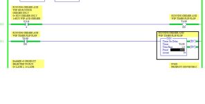
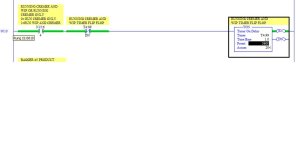
My XIO instruction addressed to T4:0/DN is always on (it is actually a panel view button pushed), how do I get my timer to reset when my input is always on.

The reset will happen. It just happens too fast for you to see. The XIO instruction will only go false for one scan. In the scan that it is false, the timer gets reset and the following scan, the instruction reverts to being true.
 
Last edited:
Change your T4:99/DN from a XIC instruction to an XIO as Steve suggested, then your timer will cycle.

The XIO looks like a normally closed contact.

Also, you shouldn't program the T4:99/DN as an OTE instruction like you have in rung 10. The TON instruction controls the /DN bit.

If you want N13:6/4 to start/stop the cycle, put it on rung 11 with the TON. Then the cycle will only run when N13:6/4 is true.

Ditto.
I kept staring at his post and shaking my head, something is wrong here. I was about to post the same answer.
Having an OTE with the timer done bit to me is akin to double coiling.
 
The logic you posted is not what I proposed back in post #8.

It also looks like you suffer from a common misconception. A lot of people see "XIO" and think "Normally Open (NO) contact; they see "XIC" and think "Normally Closed (NC) contact. The XIO instruction looks like a normally closed contact and the XIO instruction looks like a normally open contact.
 

Similar Topics

Hi We have 12x Bosch 4WRPEH 100l/min proportional valves. These valves have a 4th spool position that closes the actuator if the proportional...
Replies
6
Views
6,676
Hey all, I am starting a new project for a customer and I am adding in solenoid valves. Once added, I noticed there was a lack of an Output...
Replies
0
Views
47
Hi, The hardware is: Click Plc model # CO-O1DD1-O HMI model # S3ML-R magnetic-inductive flow meter model # FMM100-1001. I will set the flow meter...
Replies
4
Views
108
Hi, I am using AB 5069-L306ERS2 CPU. My system should achieve SIL-2. I have safety door switches connected to AB 5069-IB8S module, and I want to...
Replies
1
Views
97
Hello! Hope you are great. I need to make a change in a PLC with ladder logic. I will mount a analog valve and I need to control it in ramp up...
Replies
7
Views
281
Back
Top Bottom