Analog inout?

ilija28

Member
Join Date
Mar 2009
Location
Macedonia
Posts
13
Hi. I need to read analog input from NH3 sensor !! The output is 0-24 mV,and te range of sensor is 0-14 mg/l I need to do this with step7 v5.4,and it MUST be with LADDER logic !!! After that,i need to display the results in wincc panel ! I just need to program this,its a faculty project ! I do not need to simulate step7 and wincc,i just need panel to simulate numbers between 0 - 14 mg/l . Have anybody idea how to do this with Ladder logic in step7 v.5.4 sp1 and wincc flexible 2007 !! Thanks !!
 
Hi. I need to read analog input from NH3 sensor !! The output is 0-24 mV,and te range of sensor is 0-14 mg/l I need to do this with step7 v5.4,and it MUST be with LADDER logic !!! After that,i need to display the results in wincc panel ! I just need to program this,its a faculty project ! I do not need to simulate step7 and wincc,i just need panel to simulate numbers between 0 - 14 mg/l . Have anybody idea how to do this with Ladder logic in step7 v.5.4 sp1 and wincc flexible 2007 !! Thanks !!

I made a writing mistake,sensor output is 4 - 20 mA !!!!
 
To do what you have proposed you have to:
1. Configure your analog input card (4..20ma, address)
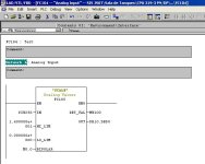
2. Write a program using FC105 (Scale) from the Simatic library (see analog.jpg).
3. Configure your panel via WinCC Flexible
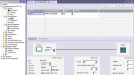
4. Configure the connection (see WinCC1.jpg)
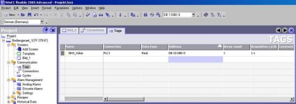
5. Configure the tag (see WinCC2.jpg)
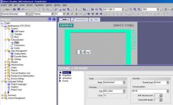
6. Create the image you want to see (see WinCC3.jpg)
7. Test it.

Good luck!

Analog.JPG Wincc1.jpg Wincc2.jpg Wincc3.jpg
 
Hi

Hello Clemens . Thanks for the time spended on my problem. I will write all my project,and hope for help from you !! I am student at mechanical facultity,for hidraulic and pneumatic,and I am not good with step7 and wincc,but I must do this project this week !! My project is to tell that is it possible to monitor river condition with step7 and wincc !! I request help for one sensor (NH3),but there are eight sensors.
1.Temperature output 4 – 20mA, range – 50 to + 50 celzius degrees
2.Level output 4 – 20 mA, range 0,91 - 76,2 meters
3. Turbidity output 4 – 20 mA, range 0 – 1000 NTU (Nephelometric turb. Unit)
4. Dissolved oxygen output 4 – 20 mA, range 0-100 %
5. NH3 output 4 – 20 mA, range 0 – 14 mg/l
6. PO4 output 4 – 20 mA, range 0,05 – 3 mg/l
7. Ph output 4 - 20 mA, range 0 – 14 (no units)
8. Flow output 12vdc,current sinking pulse (??????), range 0,06 – 9,14 m/sec.
You can see 7 sensors have output 4 – 20 mA,only one not(for flow) Maybe I will find on internet flow sensor with 4 – 20 mA output,but later for that !
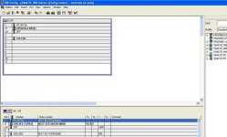
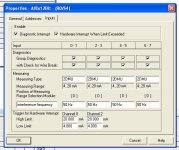
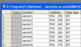
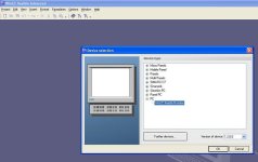
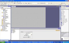
Now,your first point was to configure analog input card ????? A do not know what was that,and I do this in step 7 : I choose CPU315-2DP,and in hardware configuration I ad PS 307 5A (order number 6ES7 307-1EA00-0AA0)and analog module SM331 8 AI x 12 Bit (order number 6ES7 331-7KF00-0AB0) (pic 2),and I ad this properties (pic3).Here I set for flow output 4 – 20 mA,becose these is only school project,nobody will know the real flow sensor output ! But if you know what meens that “ 12vdc current sinking pulse”,write to me. Than in symbol table I ad this symbols :names sensors 1…..8,adresses PIW 256…..PIW 270,and data type for all “INT”. (pic 4). So,please tall me did was that for your first point : “ 1. Configure your analog input card (4..20ma, address)”. If not,please tell what I need to do !! Next,for your second point : “2. Write a program using FC105 (Scale) from the Simatic library” ,I find that funcion,but tell my how to do that with all 8 sensors !! Did I need 8 networks ??? And where to program,I thing in OB1 ?? I must store measured values in some data base,did I need to make data block for that,and what is your output “DB10.DBD0”,is that some data block where goes scalet real numbers? What will be output adress for my second sensor (second scale function in next network?) For the and of this point what is M0.0? This is universal adress for bipolar,and what I need to put for unipolar? And what is MW100 ? Please wrote me about adreses,and data base (output) . I know that you are angry for loosing time with step7 fool like me,but I am pleased for your help,and I appreciate that !! Your next point Is to configure wincc panel !! I do not know witch panel to use,so please tell me. Did you meen to choose some of this : first I go to “create empty project”,and than opens to choose some panel ( pic 5)? For example I open the last “pc-wincc flexible runtime”and opens this interface (pic 6). And for the next point,I am realy stucked (I don’t know where to look for values,what to put for adress ,and what is DB1DBW0?),so please,if you have time,send me a letter with more help,and what to do,or if you allready have step7 and wincc software,please do some simple project (just for one sensors) and send me to e-mail [email protected] or at forum,I think is more helpfull,your previous post allready view many forum members !! Thanks again for your time,if you want to help please answer me ,I need to do my project this week (until Friday). Best regards !!! P.S. Sorry for my English J

pic 2.jpg pic 3.JPG pic 4.JPG pic 5.JPG pic 6.JPG
 
Hi,

I'll write the answers in your text.

Hello Clemens . Thanks for the time spended on my problem. I will write all my project,and hope for help from you !! I am student at mechanical facultity,for hidraulic and pneumatic,and I am not good with step7 and wincc,but I must do this project this week !! My project is to tell that is it possible to monitor river condition with step7 and wincc !! I request help for one sensor (NH3),but there are eight sensors.
1.Temperature output 4 – 20mA, range – 50 to + 50 celzius degrees
2.Level output 4 – 20 mA, range 0,91 - 76,2 meters
3. Turbidity output 4 – 20 mA, range 0 – 1000 NTU (Nephelometric turb. Unit)
4. Dissolved oxygen output 4 – 20 mA, range 0-100 %
5. NH3 output 4 – 20 mA, range 0 – 14 mg/l
6. PO4 output 4 – 20 mA, range 0,05 – 3 mg/l
7. Ph output 4 - 20 mA, range 0 – 14 (no units)
8. Flow output 12vdc,current sinking pulse (??????), range 0,06 – 9,14 m/sec.
You can see 7 sensors have output 4 – 20 mA,only one not(for flow) Maybe I will find on internet flow sensor with 4 – 20 mA output,but later for that !
Now,your first point was to configure analog input card ????? A do not know what was that,and I do this in step 7 : I choose CPU315-2DP,and in hardware configuration I ad PS 307 5A (order number 6ES7 307-1EA00-0AA0)and analog module SM331 8 AI x 12 Bit (order number 6ES7 331-7KF00-0AB0) (pic 2),and I ad this properties (pic3).Here I set for flow output 4 – 20 mA,becose these is only school project,nobody will know the real flow sensor output ! But if you know what meens that “ 12vdc current sinking pulse”,write to me. 12VDC current sinking pulse means that you are talkin about a pulse signal, so it is not an analogue value. It is a digital pulse value that may be connected to a digital input card through an intermediate relay. I suggest you get an analogue signal transducer.
Than in symbol table I ad this symbols :names sensors 1…..8,adresses PIW 256…..PIW 270,and data type for all “INT”. (pic 4) I suggest you use more descriptive symbols like Water Temperature.
So,please tall me did was that for your first point : “ 1. Configure your analog input card (4..20ma, address)” The first point is OK.If not,please tell what I need to do !!
Next,for your second point : “2. Write a program using FC105 (Scale) from the Simatic library” ,I find that funcion,but tell my how to do that with all 8 sensors !! Did I need 8 networks ??? Yes, in the ladder diagram you will need at least 8 networks to make 8 independet calls to the FC105.
And where to program,I thing in OB1 ?? You may call the FC105 from the OB1, but good programming practices suggest you call the FC105 from a new function (FC1, for example) and then call the FC1 from an OB. I would use OB35, caled every 100ms in order to have a deterministic sampling of the inputs.
I must store measured values in some data base,did I need to make data block for that,and what is your output “DB10.DBD0”,is that some data block where goes scalet real numbers? Yes, you should store your values in a datablock (DB10, for example) If you store the values one after another, you'll have:
Value 1 DB10.DBD0
Value 2 DB10.DBD4
Value 3 DB10.DBD8...
What will be output adress for my second sensor (second scale function in next network?)
For the and of this point what is M0.0? It's an internal signal (marker or flag) that should be 0. It should be set to 1 if your signal is bipolar (-20mA...20mA)
This is universal adress for bipolar,and what I need to put for unipolar?
And what is MW100 ? MW100 is any word where you would have a diagnostic of your analog input. If it is not 0 your analog input is not working properly.
Please wrote me about adreses,and data base (output) . I know that you are angry for loosing time with step7 fool like me,but I am pleased for your help,and I appreciate that !! Your next point Is to configure wincc panel !! I do not know witch panel to use,so please tell me. Did you meen to choose some of this : first I go to “create empty project”,and than opens to choose some panel ( pic 5)? For example I open the last “pc-wincc flexible runtime”and opens this interface (pic 6). That is OK. Then you should define the connection from your "panel" to the PLC.
And for the next point,I am realy stucked (I don’t know where to look for values,what to put for adress ,and what is DB1DBW0?)
It should be DB10.DBD0 for your first analogue value.
,so please,if you have time,send me a letter with more help,and what to do,or if you allready have step7 and wincc software,please do some simple project (just for one sensors) and send me to e-mail [email protected] or at forum,I think is more helpfull,your previous post allready view many forum members !! Thanks again for your time,if you want to help please answer me ,I need to do my project this week (until Friday). Best regards !!! P.S. Sorry for my English J
 
Last edited:

Similar Topics

Hi, I have questions. I have Analog Input that need to put into Ignition Designer. But I don't know how to put?
Replies
1
Views
19
Omron AD081-V1 Analog Input Card Offset & Gain Adjustment Entering Adjustment Mode 1. Set the input card in adjustment mode (Turn ON Dip SW No-1)...
Replies
0
Views
15
Why AMIo800 Analog input module's I/O LED is Lighting up Red? Checked module connections, 4-20ma wires etc but this light is continuously Lighting...
Replies
1
Views
62
Hello! Hope you are great. I need to make a change in a PLC with ladder logic. I will mount a analog valve and I need to control it in ramp up...
Replies
7
Views
272
Does anyone have experience wiring this type of analog pressure transmitter up? It's 4 wires. 3 blacks and 1 green which I assume is earth...
Replies
9
Views
240
Back
Top Bottom