Modicon 984 Ladder Logic question

Ken Roach

Lifetime Supporting Member + Moderator
Join Date
Apr 2002
Location
Seattle, WA
Posts
17,482
This might be the first of many; I am learning Modicon ladder logic for a conversion project and I hope that Forum members can help me with some simple questions.

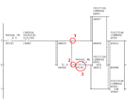
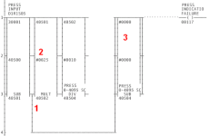
This rung scales an analog input and sets an alarm. I have three questions:

1. The lower output on a Modicon SUB instruction indicates that Value 1 is less than Value 2. So in this instruction, the branch is true if the analog input value in 30001 is less than the holding register value in 40500. Is this correct ?

2. Does this "#0025" represent a constant value ? Is it in Decimal or hex/octal/BCD ? In the A-B world, a "#" indicates an indirect or indexed value so I want to be sure about the Modicon syntax.

3. This SUB instruction appears to result in moving a zero to the holding register 40504. Is this SUB used instead of a "move" instruction to manually set 40504 to zero ?

3A. Do the three outputs "tied together" on this SUB instruction indicate that the output 00117 is true in every output case ?
modicon_rung_1.png
 
No. 1 - Correct
No. 2 - That is a constant in decimal
No. 3 - SUB's are used as moves or compares
No. 4 - It looks like if No. 1 is true then 00017 comes on.
 
Thanks, especially to jtn for confirming that the SUB instruction in Modicon 984LL is often used where LES/LEQ/GRT/GEQ/EQU or MOV might be used in an Allen-Bradley controller.

I was surprised how hard it was to find Modicon Compact user manuals (that Russian site is blocked from my work network). I never did find them from Groupe Schneider/Telemechanique/SquareD but downloaded them from Alameda Electric's website. I am fortunate to have a hardcopy of GM-A-120-LDR.

I am likely to have more questions as I go along. Thanks !
 
Okay, here we go again. This seems simple but I'm making a couple of assumptions I am not sure about.

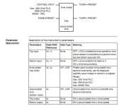
I have a Timer instruction, which looks straightforward enough; it uses a single Holding Register, I assume for the accumulated value.

1. The top output of a Timer is true when the timer is Done. This is like the /DN bit in A-B. Is this correct ?

2. The bottom output of a Timer is true while the timer is in progress. This is like the /TT bit in A-B. Is this correct ?

But following the timer, on the lower output, is an instruction that looks like a contact with a P in the middle: ]P[

3. Is this a Positive-transition one-shot ?

Any other comments about how this rung works would be appreciated.

Modicon_P_instruction.PNG
 
one thing you will need to look out for as well, is the fact that sometimes the address you see is the first of 2 consecutive addresses. The divide instruction for example.

If you see indirect addressing you may need help there too :)
 
It's been a while, but I recall that if the timer<preset output condition is true, it'll energize what follows it even if the preconditions to the timer are not true... this would seem to be why the pulse instruction is used there (as this address is also referenced as a guard to the execution of the timer).

(Make sure you also understand the order of execution of instructions in a network... down the first column, then down the second, etc.)
 
The note by jamesau highlights a FEATURE of Modicon which tripped me more than once. We normally would expect that an output (toward the right side) from an upper rung on a network would be useable in that state by a contact to the left on a rung lower down but in the same network. It isn't so. Train yourself very carefully on the 'down column 1 then down column 2 etc' scan method.
 
I think the Timer lower right output pin is true whenever the accumulated time is less than the preset, even if the timer is not 'enabled'.
 
I think the Timer lower right output pin is true whenever the accumulated time is less than the preset, even if the timer is not 'enabled'.

This is true, and the lower right timer output can be used to provide power to a rung that is not even connected to the power rail. I learned of this trick on this forum.

Brian.
 
Am I correct in inferring from the statement that the output of the timer is true when Accumulated Value = Preset that the timer stops accumulating when it reaches preset?

Presumably, if it kept accumulating up to the max allowable, the statement would be "Output is true when Accumulated Value >= Preset.

Also, if my first inference is correct, what would happen if an HMI changed the preset value to a smaller number while the timer was enabled and the output was already on. Would the accumulated value also get adjusted to keep the output true?
 

Similar Topics

Hi there and happy 2013! I was given a Modicon 984 printout. The file name of the .PDF file contains the string "Modicon 984 Proworx". I am...
Replies
6
Views
4,563
Hi, Seeking consultation on an implementation matter, and have a question about Modicon Compact 984 communication through RS485: Three Modicon...
Replies
4
Views
199
Hi I have a modicon 984 with proworx 32 that is scaling an analog input, and I need to adjust the scaling. I have new analog input values and %...
Replies
3
Views
1,721
Hi, I am trying to get a machine started that was moved from one location to another. It has a Modicon 984-A131 PLC. I have Schneider Electric...
Replies
1
Views
1,010
Dear Friends, I have Schneider PLC which is the world's first one Modicon i need software of Modicon PLC 984,it is known as...
Replies
0
Views
962
Back
Top Bottom