Ron Beaufort
Lifetime Supporting Member
Greetings to all ...
I got this in a PM the other day ... since the question is a rather common one, I decided to answer it here in the open forum where hopefully it will benefit more than just one reader ...
I don’t have time to go through the entire setup for PIDE but I’m attaching some material that I’ve been developing for an upcoming class for a customer ... these are basically “lab notes” for use in hands-on exercises – and NOT a “textbook” ... please note that this is NOT completely finished – but maybe it will be helpful ... also, if there are any typos, etc. please feel free to point them out ...
the PDF file attached shows enough (hopefully) about how the “control bits” should be set up in order to gain AUTO and MANUAL control – both WITH and WITHOUT “bumpless” transfers between the auto and manual modes ...
before we go any further, here’s my personal opinion on the use of “bumpless” transfers ... sometimes it’s a good idea ... at other times it’s a bad idea ... I’ve actually heard of a few cases where a programmer has gone to a fair amount of effort to provide bumpless transfers – and then had to go back later and remove that capability when the operators complained about it ...
suppose that the system being automatically controlled has a well-established setpoint which never (or at least hardly ever) needs changing ... let’s say that the automatic setting is 350 degrees just to have a number for discussion ...
now suppose that from time-to-time the operator needs to put the system into manual operation – and that the manual setting is also well-established and hardly ever needs changing ... let’s say that the manual setting is 20% just to have a number for discussion ...
so – day after day – the operator runs the system in automatic – and occasionally switches it over to manual operation ... basically all he has to do is flip a switch from one mode to another – and if there happens to be a “bump” when going from one mode to another, then that’s quite OK (at least for THIS particular system) ...
next a young programmer “new and improves” the system – and along the way “bumpless” transfer gets incorporated ...
now look what happens the next time the operator flips the switch into manual mode ... instead of getting the old familiar 20% value for the output, now he gets whatever value the system happened to be running along at the instant the change to manual mode was made ... so now, instead of just flipping the “manual” switch and going on about his business, the operator is forced to tweak and twiddle an extra control to dial in the desired 20% output ...
and ...
the next time the operator flips the switch into automatic mode, instead of getting the desired 350 degree setting, now the setpoint stays at whatever value the system happened to be running along at the instant the change to the automatic mode was made ... once again, instead of just flipping the switch into “automatic” and moving on, the operator has to tweak and twiddle yet another extra control to dial the setpoint back to where it’s supposed to be ...
disclaimer: notice that I am NOT saying that “bumpless transfer” is a dumb idea ... in some (in many?) cases it’s completely NECESSARY ... all I’m saying is that just because it “sounds cool” is no reason to set it up on every system that comes along ...
anyway ... see if the attached files make sense, and if you have any specific questions, please ask them here on the open forum where others can benefit – especially from what other forum members can add to the conversation ...
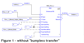
Figure 1 shows a BASIC DOWN-AND-DIRTY set up WITHOUT bumpless transfer ...
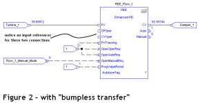
Figure 2 shows another BASIC DOWN-AND-DIRTY set up – this time WITH bumpless transfer ... notice that the HMI/SCADA is connected directly to the INTERNAL addresses of the PIDE control – and does NOT use input references for the Setpoint or the Manual CV settings ... if you decide to use input references, you’ll probably have to come up with some means of disconnecting them when they’re not being used ... with many HMI/SCADA systems, if you use them and leave them connected, they’ll tend to overwrite any “present” values that the PIDE tries to store – which usually defeats the “bumpless transfer” idea ...
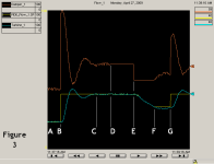
Figure 3 shows a trend of a system with “bumpless transfer” – based on controlling the Air Flow section of the Ramrod simulation that we’ve discussed before ... from A to B the system is under automatic control – and “on target” ... at B the setpoint is changed from 20% to 40% of full flow ... at C the system has settled down at the new setpoint ... at D the system is switched to Manual mode – notice that the CV (orange) holds steady at its present value ... in other words, no “bump” to the system when going from auto mode to manual mode ... at E the CV is manually moved to a new setting ... notice from D to F that the Setpoint is hidden behind the PV (blue) ... during that portion of the trend, the setpoint is “following” or “tracking” the PV ... at F the system is switched back to the Automatic Mode ... notice that the Setpoint (yellow) holds steady at its present value ... in other words, no “bump” to the system when going from manual mode to automatic mode ... at G the setpoint is manually raised to a setting of 40% ...
hope this helps ...
I got this in a PM the other day ... since the question is a rather common one, I decided to answer it here in the open forum where hopefully it will benefit more than just one reader ...
The ProgValueReset bit
Hi Ron,
When going over the pdf of PIDE States Modes you posted some time ago I still have my mind unclear about a little issue...The ProgValueReset bit: is it for setting it to true in the exact point of time at which I toggle the auto mode to manual? Is it like that how we avoid the bumping when we operate this change from auto to manual? I also understand that additionally the PVTracking bit must be set to true. Is this right?
I'm just implementing all the knowledge I've been gathering from your posts and from other members of the forum too in my first project using the PIDE instruction and so far it is going fine unless for this little issue I've not been yet able to solve by myself.
Thanks again for you attention and your time at reading this,
I don’t have time to go through the entire setup for PIDE but I’m attaching some material that I’ve been developing for an upcoming class for a customer ... these are basically “lab notes” for use in hands-on exercises – and NOT a “textbook” ... please note that this is NOT completely finished – but maybe it will be helpful ... also, if there are any typos, etc. please feel free to point them out ...
the PDF file attached shows enough (hopefully) about how the “control bits” should be set up in order to gain AUTO and MANUAL control – both WITH and WITHOUT “bumpless” transfers between the auto and manual modes ...
before we go any further, here’s my personal opinion on the use of “bumpless” transfers ... sometimes it’s a good idea ... at other times it’s a bad idea ... I’ve actually heard of a few cases where a programmer has gone to a fair amount of effort to provide bumpless transfers – and then had to go back later and remove that capability when the operators complained about it ...
suppose that the system being automatically controlled has a well-established setpoint which never (or at least hardly ever) needs changing ... let’s say that the automatic setting is 350 degrees just to have a number for discussion ...
now suppose that from time-to-time the operator needs to put the system into manual operation – and that the manual setting is also well-established and hardly ever needs changing ... let’s say that the manual setting is 20% just to have a number for discussion ...
so – day after day – the operator runs the system in automatic – and occasionally switches it over to manual operation ... basically all he has to do is flip a switch from one mode to another – and if there happens to be a “bump” when going from one mode to another, then that’s quite OK (at least for THIS particular system) ...
next a young programmer “new and improves” the system – and along the way “bumpless” transfer gets incorporated ...
now look what happens the next time the operator flips the switch into manual mode ... instead of getting the old familiar 20% value for the output, now he gets whatever value the system happened to be running along at the instant the change to manual mode was made ... so now, instead of just flipping the “manual” switch and going on about his business, the operator is forced to tweak and twiddle an extra control to dial in the desired 20% output ...
and ...
the next time the operator flips the switch into automatic mode, instead of getting the desired 350 degree setting, now the setpoint stays at whatever value the system happened to be running along at the instant the change to the automatic mode was made ... once again, instead of just flipping the switch into “automatic” and moving on, the operator has to tweak and twiddle yet another extra control to dial the setpoint back to where it’s supposed to be ...
disclaimer: notice that I am NOT saying that “bumpless transfer” is a dumb idea ... in some (in many?) cases it’s completely NECESSARY ... all I’m saying is that just because it “sounds cool” is no reason to set it up on every system that comes along ...
anyway ... see if the attached files make sense, and if you have any specific questions, please ask them here on the open forum where others can benefit – especially from what other forum members can add to the conversation ...
Figure 1 shows a BASIC DOWN-AND-DIRTY set up WITHOUT bumpless transfer ...
Figure 2 shows another BASIC DOWN-AND-DIRTY set up – this time WITH bumpless transfer ... notice that the HMI/SCADA is connected directly to the INTERNAL addresses of the PIDE control – and does NOT use input references for the Setpoint or the Manual CV settings ... if you decide to use input references, you’ll probably have to come up with some means of disconnecting them when they’re not being used ... with many HMI/SCADA systems, if you use them and leave them connected, they’ll tend to overwrite any “present” values that the PIDE tries to store – which usually defeats the “bumpless transfer” idea ...
Figure 3 shows a trend of a system with “bumpless transfer” – based on controlling the Air Flow section of the Ramrod simulation that we’ve discussed before ... from A to B the system is under automatic control – and “on target” ... at B the setpoint is changed from 20% to 40% of full flow ... at C the system has settled down at the new setpoint ... at D the system is switched to Manual mode – notice that the CV (orange) holds steady at its present value ... in other words, no “bump” to the system when going from auto mode to manual mode ... at E the CV is manually moved to a new setting ... notice from D to F that the Setpoint is hidden behind the PV (blue) ... during that portion of the trend, the setpoint is “following” or “tracking” the PV ... at F the system is switched back to the Automatic Mode ... notice that the Setpoint (yellow) holds steady at its present value ... in other words, no “bump” to the system when going from manual mode to automatic mode ... at G the setpoint is manually raised to a setting of 40% ...
hope this helps ...


