1 Button / 1 Rung Control

Terry Woods

Member
Join Date
Apr 2002
Posts
3,170
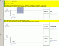
Here's another stab at trying to make the 1-Button/1-Rung Control thing more understandable.

It doesn't matter if you are in favor of using SET/RESET (Latch/Unlatch). The fact is, at least with some PLC's, you can do this.

AND, as with ALL things that you should be careful with (don't run with scissors! You'll put your eye out!), be careful... follow the rules and maintain your house-keeping!

3d1cfe6d4acaac97.gif


This code is a direct implimentation of the following FlowChart.
This thing works. I have it running right now on an S7-200.

3d1cfec24b300d7f.gif


Use ALL of the tools that are available to you - but be damned careful how you use them!

If you want a step-by-step explanation, just say so. I'll even throw in a timing diagram if you want.

BTW, Peter, is the more appropriate term... "Re-Entrant"?

I know damned well that there is a term that is applied to what I was describing.
 
Terry Woods said:
BTW, Peter, is the more appropriate term... "Re-Entrant"?

I know damned well that there is a term that is applied to what I was describing.

No, again re-entrant applies to subroutines. A re-entrant subroutine has its own local variables and can be interrupted and then called again from the interrupt routine and still work properly. A S7-300 function can be re-entrant if it doesn't modify global memory. A S7-300 function block is not re-entrant if it modifies variables in its DB or globals memory.

I know the what you are trying to say. This is a PLC Ladder Compiler problem.


This is easy

IX0 OX0
--------||-----------------------()
| IX1 OX1
+-----||---------()

ld ix0
st ox0
and ix1
st ox1

No pushes pope or temporary coils required.


This is not

IX0 IX1 OX0
--------||------------||---------()
| OX1
+----------------()

ld ix0
push
and ix1
st ox0
pop
st ox1

Note that push and pop are not IEC 61131-3 instruction list instructions.

This can also be broken down into two rungs.

IX0 IX1 OX0
--------||------------||---------()

ld ix0
and ix1
st ox0

IX0 OX1
--------||-----------------------()

ld ix0
st ox1

This is the problem Terry is talking about. To avoid non standard push and pop, one must use two rungs. No big deal. Code wise two rungs would be more effiecient.


If the rung is modified by switching the two branches then this
rung is easy but then the outputs are updated in reverse order.
Is it OK for the compiler to switch the order of updating the outputs
just to avoid the push and pop or two rungs.

IX0 OX1
--------||-----------------------()
| IX1 OX0
+-----||---------()

ld ix0
st ox1
and ix1
st ox0


Now lets go a step further.

IX0 IX2 OX0
--------||------------||---------()
| IX1 OX1
+-----||---------()

If the PLC uses non-standard push and pop instructions then

ldi ix0
push
and ix2
st ox0
pop
and ix1
st ox1

Without the non standard push and pop the compiler forces the user to use two rungs:


IX0 IX2 OX0
--------||------------||---------()

ld ix0
and ix2
st ox0

IX0 IX1 OX1
--------||------------||---------()

ld ix0
and ix1
st ox1


I think the term Terry is look for is nesting. The push and pop allows nesting the condtion registers in a similar way parentheses allow nesting in formulas.

Telemechanique uses three instructions MPS , MRD, and MPP. These are equivelent to push , pop push and pop. None of these instructions are in my IEC 61131-3 documentation. Telemechanique instruction list is non standard but these three instructions are required if more complicated rungs with multiple output are desired.

MPS, MRD, MPP, push and pop are stack instructions. These are dangerous instructions that can cause stack over and underflows as in forth. This is probably why stack instructions are not included in the IEC 61131-3 specification. Be carefull when using stack instructions.

I see differing opinions about rungs with multiple outputs. It does not make any difference when using a ladder compiler but multiple outputs in instruction list can be unsafe if stack instructions are used.

I am working on an IEC compatible package. I think I will implement just the standard. This means non-standard stack instruction will not be available. This also means that mulitple output rungs may not be available, unless the ladder compiler can convert the mulitple output rung and break it down to multiple rungs with one output each and hide this from the user. Any thoughts?

Hopefully this gives everyone some insight into why....

Terry, I just got some new S7-200 software but haven't tried it out yet. Can it do flow charts too?
 
Last edited:
Couldn't you use 2 one shots something like this.....


B3:3/0 B3:3/0
-------[Pb]--------------[/]----[ONS)-----(L)-----
| |
| |
|--[]----[ONS]-----(U)--
B3:3/0 B3:3/0


or a counter :)


--------[Pb]------------[ONS]-------[CTU] PRE=2---
| |
| CTU/ACC=1 B3:3/0 |
|--[EQU]-------(L)-----------
| |
|CTU/DN B3:3/0 |
|--[]---------------------
| |
|CTU/DN B3:3/0 COUNTER |
|--[]-----[/]------[RES]-----
 
Sorry.. but the graphics didn't turn out the way they did when I worked them up...
on the first example the branch was supposed to go around the XIO (for B3:3/0) so that the first rung conditional was (xic(pushbutton)---xio(b3;3/0---ons---Latch(b3:3/0))..
the second rung was supposed to start before the xio and have as conditionals the pushbutton(to make the rung true) and xic for B3:3/0) a ons and then an Unlatch... so rung two(branch) should be (xic(pb)---xic(b3:3/0)--ons---(Unlatch b3:3/0).


in the second example I used a xic(pb)---ons--ctu(countup with a preset of 2).I branched a rung below it that had an [equ] so if ctu=1 then b3:3/0 was Latched (L).... so then if the pb get tapped again.. ctu=2.. and ctu/dn goes high.. so on the branch below the Latch is an unlatch with the conditional xic (ctu/dn)..then an Unlatch (B3:3/0)...
then the final branch has 2 conditionals.. (xic ctu/dn) and (xio that B3:3/0 is unlatched).. then I reset (res ctu).. so the whole thing can start over.


not as eloquent as the flip flops.. true.. but it works fine. :)


Russ
 
Peter,

I don't know that S7-2xx can manage FlowCharts. I simply use FlowCharts as one of my basic tools! While FlowCharts might not apply so directly in some PLC's, they do seem to apply in a very straight-forward manner in the S7-2xx. I can't speak to the S7-3xx or -4xx.


Russ,

Please try to post your code again. You need to delimit the code-area by using [ code] ...your code...[/code ] like so...


[ code] <-- Type in as shown WITHOUT the leading space!

Your Ladder Code will come out looking like this...
Code:
---| |---+---| |---(  )
         |
         +---------(  )
[ /code] <-- Type in as shown WITHOUT the leading space! And don't forget the slash!


You can use the word "ladder" instead of "code" if it suits you better. However, notice the font size difference. You can change that by using [ SIZE] [ /SIZE] (Don't forget to remove the leading spaces.)

[ ladder] <-- Type in as shown WITHOUT the leading space!

Your Ladder Code will come out looking like this...


Small Font Size (DEFAULT)
[ SIZE=1]
---| |---+---| |---( )
|
+---------( )
[ /SIZE]


Large Font Size
[ SIZE=3]

---| |---+---| |---( )
|
+---------( )
[ /SIZE]


Huge Font Size
[ SIZE=4]
---| |---+---| |---( )
|
+---------( )
[ /SIZE]


[ /ladder] <-- Type in as shown WITHOUT the leading space! And don't forget the slash!

Before posting a question or response, it is very beneficial to you and us if you "Preview Reply" before "Submit Reply".

In the making of this reply to you, I "Previewed" at least 50 times.

You would do well to read up on the HTML and vB coding available.
 
Last edited:
Ahhh... thanks Terry... :)


Code:
                         B3:3/0               B3:3/0 
-------[Pb]--------------[/]-------[ONS)-----(L)----- 
                       |                         | 
                       |                         | 
                       |                         |
                       +--[]-------[ONS]-----(U)-+  
                          B3:3/0              B3:3/0 


or a counter  


        Momentary
        Pushbutton                  Preset of 2
--------[Pb]------------[ONS]-------[CTU]----- 
                     |                      |
                     |                      | 
                     | CTU/ACC=1     B3:3/0 | 
                     +--[EQU]-------(L)-----+ 
                     |                      | 
                     |                      |
                     |CTU/DN         B3:3/0 | 
                     +--[]-----------[U]----+ 
                     |                      | 
                     |                      |
                     |CTU/DN B3:3/0 COUNTER | 
                     +--[]-----[/]----RES]--+


Though with the counter I guess you could have 1 push button initiate a bunch of sequential outputs if you wanted that..

Thanks Terry for the [ code] [ /code] tips.. :)

Russ
 
Russ said:
Ahhh... thanks Terry... :)


Code:
                         B3:3/0               B3:3/0 
-------[Pb]--------------[/]-------[ONS)-----(L)----- 
                       |                         | 
                       |                         | 
                       |                         |
                       +--[]-------[ONS]-----(U)-+  
                          B3:3/0              B3:3/0

In your example,
If PB is ON then check B3:3/0.
If B3:3/0 is OFF then One-Shot to Latch B3:3/0
Fine, if the light ain't ON when the PB is pushed then turn the Light ON.
Now, depending on your PLC, this is where the problems begin...
Some PLC's simply bail out of the rung after executing the first branch of the rung.
Other PLC's continue to evaluate the remaining branches!
In your example, in the first branch, if Light OFF, then Light ON.
"Other" PLC's would then go on to evaluate the following branch where the Light would be seen to be ON and therefore another One-Shot is applied to turn the Light OFF. The Light will NOT go ON - it will always be OFF.


Code:
or a counter  


        Momentary
        Pushbutton                  Preset of 2
--------[Pb]------------[ONS]-------[CTU]----- 
                     |                      |
                     |                      | 
                     | CTU/ACC=1     B3:3/0 | 
                     +--[EQU]-------(L)-----+ 
                     |                      | 
                     |                      |
                     |CTU/DN         B3:3/0 | 
                     +--[]-----------[U]----+ 
                     |                      | 
                     |                      |
                     |CTU/DN B3:3/0 COUNTER | 
                     +--[]-----[/]----RES]--+

I don't see a problem with the counter code.

Though with the counter I guess you could have 1 push button initiate a bunch of sequential outputs if you wanted that..

A counter can provide an easier way to execute a series of steps, but you should also monitor conditions. While the counter method is easier, simply watching for the PB does not watch for input conditions other than the PB.

Thanks Terry for the [ code] [ /code] tips.. :)

Russ
 
Naturally I am confused

In this picture Terry posted:
onerungtoggle.gif

Is WAS meant to act as the one shot?

I have a couple S7-200's but no working software to use with them so cant test it. I will try this on the PLC I am presently working with.

I am having problems with "nesting" or branching around its Positive transition coil with the software, it allows the multiple outputs on the end but not branching coils or adding separate conditions to the coils. I am still learning this software though. If you are curious about it then you can obtain it free at www.heapg.com. Its called CScape.

I am saving this page to Favorites with OFFLINE viewing to better understand some of what has been stated.
 
This is how i would do it in an Omron PLC.

Two different versions.
1st Rung will work in a CJ1/CS1 PLC only.
The 2nd verion (rung 2&3) will work for all current Omron PLC's.

Download code from here if you like.
Download Code

toggleoutput.gif
 
Ron,

The short answer is... no. The "WAS" bit is not a one-shot.

Once the PB is pressed, "WAS", in the bottom branch, is turned ON and remains ON until the PB is released.


BRANCH-1:
The fact that "WAS" was OFF when the PB was pushed allows for "FLIP" to be SET. (Actually, "FLIP" does not need to be SET for this to work.) The result is "FLIP" is turned ON.

This initiates a "one-shot effect" on the "FLIP" bit. This is NOT a typical one-shot... at least, not in PLC terms. The output of a typical one-shot is ON for one full scan - from the point of creation to the point of creation.

This "FLIP" bit doesn't even stay ON 'til the next rung! If you examine the state of the "FLIP" bit at any other part of the program, at any time, the state will always be OFF. If you wanna get crazy... you could use that bit as an "ALWAYS OFF" bit!


BRANCH-2:
( still in the same scan of the same rung...)
With the "FLIP" bit ON, the branch might provide a path of TRUE's.

If "LIGHT" is NOT ON then "LIGHT" is SET ON and the "FLIP" bit is explicitly told to turn OFF (RESET).

On the other hand...
If "LIGHT" is ON then the branch does not provide a path of TRUE's and the outputs at the end of that branch will not do as indicated. That is, "LIGHT" does not get SET ON and "FLIP" is not turned OFF.


BRANCH-3:
( still in the same scan of the same rung...)

If "LIGHT" was OFF in the previous branch, then "FLIP" has been turned OFF and this branch can't provide a path of TRUE's. The outputs at the end of that branch will not do as indicated. That is, "LIGHT" does not get turned OFF (RESET) and "FLIP" is not turned OFF (again).

On the other hand...
If "LIGHT" was ON in the previous branch then that branch did not provide a path of TRUE's and the outputs at the end of that branch did not do as indicated. That is, "LIGHT" was not turn ON (again) and "FLIP" was not turned OFF (RESET).

So, if "FLIP" is still ON, and "LIGHT" is ON then "LIGHT" is turned OFF (RESET) and "FLIP" is explicitly told to turn OFF (RESET).

In either case, Branch-2 or Branch-3, FLIP is explicitly turned OFF (RESET)


BRANCH-4:
( still in the same scan of the same rung...)
Then, returning to the last branch, the PB is ON so "WAS" is ON.


NEXT SCAN:
On the next scan, if PB is still ON then "WAS" is still ON. Since "FLIP" was turn OFF in the last scan and there is no cause to turn it on now, the rest of the rung (except the last branch) is ignored. The last branch of course maintains "WAS" as long as PB is ON.


LATER SCAN:
Eventually, a scan occurs where PB is OFF. In that case, all branches except the last are ignored. In this case, the "WAS" bit goes OFF because the PB is OFF.

So... was there a one-shot in there?

The closest thing to a one-shot in there was the "FLIP" bit. But it sure wasn't on for a full scan!

Maybe it was a "premature flipping one-shot"?
 
Maybe you could call it a "Local One-Shot", since it only has an effect within THAT rung?... :confused:

Ron, Terry's example might be easier to grasp if you look at it as separate rungs. Like this:

| PB WAS
|----] [--------]/[---------------------( S ) FLIP
|
| PB FLIP LIGHT
|----] [--------] [--------]/[----+-----( S ) LIGHT
| |
| +-----( R ) FLIP
|
| PB FLIP LIGHT
|----] [--------] [--------] [----+-----( R ) LIGHT
| |
| +-----( R ) FLIP
| PB
|----] [--------------------------------( ) WAS


beerchug

-Eric
 
Russ, an easier way to use a counter is to just count up with the pushbutton, and use the 0 bit of the ACC word. Every time the binary number increases the 0 bit changes state from 0 to 1, 1 to 0, and so on. Any reason to quickly turn the output off is as easy as a RESet.


        PB                     __Counter 1_______
-------| |---------------------| CTU C5:0 |-------
| | Pre 9999 |
| | Acc 5 |
| |_________________|
|
| C5:0.Acc/0 Output
|------------| |----------( )---------

 
Last edited:
You could also use a sequencer output funtion. It has bit mask, etc...

Makes that there program fun to trouble shoot 🔨
 
Last edited:
Technically when I dont understand a branched circuit and its effects I do just that, break it down into separate rungs. The software I have to use NOW doesnt like/wont allow branched (or nested I think is the correct term) outputs.

I couldnt get my GE/Horner product/software to accept this programming but NOTE I do have the 2 rung working using the Posititive transition coil.

I havent tried the counter aspect but if its a one PB need I dont see an advantage...but:
Though with the counter I guess you could have 1 push button initiate a bunch of sequential outputs if you wanted that..

A counter can provide an easier way to execute a series of steps, but you should also monitor conditions. While the counter method is easier, simply watching for the PB does not watch for input conditions other than the PB.
Depending on situation and conditioning this could be useful.
 

Similar Topics

Hello, I'm using FactoryTalk View ME V10. I created a valve as a global object with multiple parameters and when the object is being used at the...
Replies
2
Views
120
FactoryTalk View ME running on PanelView Plus 7, connected to Compact GuardLogix 5380 PLC Customer is asking for a physical push button to be...
Replies
6
Views
181
Hi everyone Is it possible to change a button image in FactoryTalk View SE (v13.00) using VBA?
Replies
0
Views
80
I was looking for this function, so that i doesn´t need to do it in the PLC. If there are an alarm in the alarm list, i want to flash the...
Replies
2
Views
524
Hi, I'm just looking for a simple way to make a button in excel (via VBA I presume) to toggle a bit in RSLogix 5000. I just got FactoyTalkLinx...
Replies
9
Views
542
Back
Top Bottom