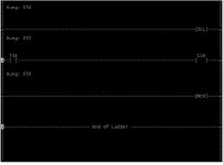
Pcis dilemma

spice_miner

Member
Join Date
Aug 2006
Location
Iowa
Posts
45
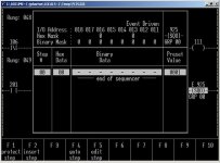
I have an old SLC 150 that I have to convert the program to RSlogix 500. There is a SQO that i don't understand.
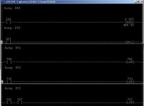
If you select "display special" on the SQO, it shows zeros in the hex mask for I/O 16 and 13. Maybe somebody can explain this to me. I'll post a screen shot of the SQO and the ladder logic..and post the whole file. Thanks.
pcis001.jpg 101739.jpg 101739.1.jpg
 

Attachments

  • slc100.zip
    70.2 KB · Views: 61
Thanks guys. I had already read the threads Ron pointed to. The search function gives me different results from the same query sometimes. Anyway I'll keep reading. The set up is a 72 valve can filler with a star wheel infeed. So the wheel is indexed to the filler pockets (valves). There is a prox on the infeed star that checks for the presence of a can. If there is a can it shifts the data 9 or 10 valves and then energizes the valve opening solenoid.You don't want a valve open if there isn't a can present. So you could be missing every other can and it would energize or not energize the solenoid at the appropriate time. A/B manuals leave a lot to be desired.
 
According to the book, the SQO instruction can be cascaded to control more than 8 outputs. In their example, they set up 3 SQO instructions, all with the same bit address. They call the first SQO instruction a dummy sequencer and go on to explain:

"With cascaded SQO instructions, bit addresses controlled by the 2nd, 3rd, and subsequent sequencers are set in the same I/O scan; bit addresses controlled by the 1st sequencer are set one scan later. This is the reason we've made the rung 1 sequencer a dummy. It controls no bit addresses. It serves only to synchronize the setting of bit addresses of the sequencers in rungs 3 and 4."

So that might be the reason your example sequencer has a mask of zero. It may be a dummy sequencer like the example in the manual.

Paul
 
Your right about the dummy SQO. It doesn't control any bits with a hex mask of zero and zero. It controls the opening latch shift register. There are 3 8-bit shift registers cascaded in the program. I didn't understand why they needed 24 bits but it is a canned program for many applications. We energize an output on the 10th bit. They have all the shift register logic nested inbetween two ZCL's. I am assuming that the ZCL will halt the shift registers and freeze the outputs if the SQO has stopped transitioning(no cans coming into the machine). Why have the ZCL's? It would still write zeros to the shift register if there are no cans coming into the filler. Instead they use the ZCL's to stop the process. Confusing..........
 

Similar Topics

I have the PCIS software on a windows 7 64 bit laptop. In my experience with other DOS based software they will not work in DOSBOX on a 64 bit...
Replies
11
Views
2,490
We have an old machine that has a SLC 150 in it and it went down with a fault today of no program. We have the pcis software on an old windows 95...
Replies
6
Views
2,729
Hello All, I am attempting to upload from a SLC 100. I know the controller is good because it is still in operation. I know the programming port...
Replies
4
Views
3,412
Hello i have finally got dosbox and pcis working properly and communicating with the slc. Dosbox did not like the usb to serial convertor i was...
Replies
2
Views
1,607
I read that you can down load PCIS from Allen Bradley for free. Its software for a SLC 100 150 PLC? Does any one know where to go to get it...
Replies
3
Views
1,699
Back
Top Bottom