DL205 directsoft5 C-More EA7-S6C

wildcatherder

Member
Join Date
May 2009
Location
Morro Bay
Posts
168
Although I have programmed in a variety of higher level languages and have gone through several PLC ladder-logic tutorials, I have found nothing about interaction between the DL205 (using a D2-250-1 CPU) and the C-More EA7-S6C touch panel. The Touch Panel manual is hardware and self-programming oriented. The DirectSoft manual seems to leave external interface panels as "an exercise for the reader".

I understand that each object on the screen has a memory address and for simple on/off inputs and outputs that is clear enough. What I need is an example of the ladder-logic - just a screen capture would be great (because few people are still using DirectSoft5) showing how to read and write Numeric Inputs and Outputs from/to the Touch Panel.

I have searched the AutomationDirect and HostEngineering forums with no joy.

Any assistance would be appreciated.
 
Wildcatherder - your posts here, on the AutomationDirect forum and on the Host Engineering forum seem to show a fundamental misunderstanding about the role of the display panel in relation to the PLC. After this please confine your posts to one forum, choose which and post that fact to the other forums.

In the normal Display-PLC setup the PLC is the place which holds all the information regarding values.

Let's discuss display and input objects on the display (the C-More in this case).

On the C-More a display object is programmed to look at an address WITHIN THE PLC. The display, at run time, asks the PLC for that value which is at that address and displays it. The PLC does not actively SEND the value to the display except in response to a request from the display.

An input object (let's say a number) is programmed such that, once a number is entered by the operator, to send that number to a specific location within the PLC. (As a help the input object may have asked for and displayed the current value - similar to an display object - from the PLC). The PLC does not actively request from the display the value. The value is sent by the display into the PLC.

As I said before - you must understand the relationship of which hardware item (the display) initiates any communication and which item (the PLC) responds to those requests.
 
Let me expand on my previous reply.

Typically there does not have to be any extra ladder logic in the PLC for the display to perform its communication. The responding by the PLC to queries happens automatically by the PLC system.

When you are creating tags in the display program and enter an address, that address is the location of the information within the PLC. I can't tell if possibly you thought that the display had a set of memory locations with coincidentally similar nomenclature.
 
In fact, there are memory locations in the touch screen but they are MAPPED to locations in the PLC, in a transparent fashion. My fundamental misunderstanding is that I asked for a simple example and not an explanation of my ignorance and thought this was a place I could get it.
 
I'm sorry that I must have misunderstood your intent in your sentence...
What I need is an example of the ladder-logic - just a screen capture would be great (because few people are still using DirectSoft5) showing how to read and write Numeric Inputs and Outputs from/to the Touch Panel.
... since no ladder-logic is used in the transfer of information to/from the display. Maybe you can set me straight on what you need.
 
In fact, there are memory locations in the touch screen but they are MAPPED to locations in the PLC, in a transparent fashion. My fundamental misunderstanding is that I asked for a simple example and not an explanation of my ignorance and thought this was a place I could get it.

From your original post, it appears that you want a screenshot of the ladder logic used to move numbers, bits, etc. to the touch screen. You will NEVER FIND this example because you do not use ladder logic or directsoft to program a touchscreen. Bernie is right when he says that you don't need any ladder logic present in the PLC for the touchscreen to communicate. You DO however need a completely separate software package to program the touchscreen. The manual for that software will explain how to connect objects on the screen to memory registers in the PLC. This is what creates the mapping you referred to in your latest post. The mapping doesn't exist without you creating it. It is not as if you can copy V2000 to V40000 and have it show up on your panel.

Now, it is possible you understood all this to begin with. If so, you didn't make that understanding very clear when you are asking for ladder logic screenshots and mentioning DirectSoft, a PLC programming package only. Also, you only ever mentioned reading the manual for the touchscreen (which only gives information on the hardware portion of the screen, not the programming) and the help in directsoft (which is the programming software for the PLC.) So forgive Bernie if he thinks you have some gaps in your understanding of how this stuff works; I thought the same thing.

Brian
 
The help file in the CMore software is very detailed. Also there are several sample projects in the Cmore projects directory.

As others have mentioned, the Cmore initiates all "conversations" with the PLC and will read/write directly from the PLC memory. You will make tags to address the User Defined memory areas that you want data transferred from/to in the Cmore software. There is no ladder logic involved.
 
Simple example of basic operation

I have a numeric input, a numeric display, and a pushbutton.
What would the ladder logic look like to add the number 2 to the value entered on the numeric input and have it appear on the numeric display?

I know this is very, very simple, if you have already done it once.

Please show me how it is done, once.

Thank you.

Sorry, too simple. Addition should occur when button is pushed.

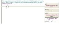
Ok, I will make the following assumtions about your system. If any of these are incorrect, you will have to adjust the rung accordingly.

Your pushbutton is set to turn on (and leave on) bit C0 in the PLC. This would not be a momentary pushbutton.
Your numeric input is set for 16 bit BCD Integer, no decimal places and pointed at V1400.
Your numeric display is set for 16 bit BCD Integer, no decimal places and pointed at V1401.
The number 2 that you want added is a constant, never changing number.


If you have any questions on this, let us know.

Brian

add example.JPG
 
Thank you all for answering my simple question. Seeing one (or, in this case a few) examples is really all I needed to get started. As an expert, one takes for granted that elements of layout, vocabulary, etc. are just not that obvious.

I know because, believe it or not, I am expert in certain areas and have made similar assumptions.

Thanks again.
 
Here's a bit of code that will do what you're looking for. Just substitute the appropriate addresses, depending on your particular system.

I will assume that in your example, you have your HMI pushbutton to be set for momentary. In this case, the bit associated with the pushbutton will be changed to ON for as long as the pushbutton is held down on screen. When the pushbutton on screen is released, the bit is changed to OFF. With the ladder setup as shown in your example, the addition operation will happen _every scan_ that the pushbutton is held down for. In this instance, it will not matter. The end result will be the same for each scan, whether it is one scan or hundreds (very possible.) However, if you setup a button to increase a register with a similar ladder setup (not the Inc/Dec funtion Bernie mentioned) multiple executions would be bad. An example would be: LD V1400, Add K2, OUT V1400. In this example, V1400 would increase for every operation. In cases like this, use the ladder setup that I gave and the operation should only occur once.

Brian
 
Why one needs simple examples - #1

The OUT command gives the error "Invalid Element" when I try to load the original address of my Numeric Display: V10016.

I changed the C-More project to use V1400 and V1401 for my numerics, as in the example from Brian123 but got the same "Invalid Element" error when trying to enter the OUT instruction. (I'm also unsure that one can actually address two 16-bit displays one bit apart doesn't work when the second is V1416 either.)

Any suggestions? This is on DirectSoft5 with the C-More EA7 panel.
 

Similar Topics

Hello everyone! I need to connect to a DL205-1 CPU and, as far as I know, I need to use DirectSOFT 6 software for the connection. Is anyone...
Replies
1
Views
60
I have some AD Direct Logic 205 series processors, racks and I/O cards, etc. that I used for development previously. It's (almost) useless to me...
Replies
16
Views
4,488
I have an older G310 - so stuck with Crimson 2, but although it is not nearly as cool, I'm doing ok with it. The issue I have is that I have a...
Replies
3
Views
2,488
Does anybody have a schematic for the power supply output in a DL205 rack? This one is the 24DC version, but the standard 120V version would do as...
Replies
2
Views
1,736
Hello PLCs. I need assistant with my current problems with the H2-ECOM100. Machine configuration: DL205 with DL240 cpu, and H2-ECOM100 plugged...
Replies
11
Views
3,670
Back
Top Bottom