pump start and valve position question

indubasu

Member
Join Date
Aug 2008
Location
Fort St. John, BC
Posts
45
1. I need to start a pump by turning on a bit from the HMI (i.e. issue an HMI command) and keep it running for 3 hrs and then unlatch this bit after 3 hrs.
2. Before this pump starts to run I need to ensure that a couple of valves are open in order for the pump to run.
3. Before issuing the HMI command for the pump to start running, the two valves called suction valve and alternate suction valve can be in any position i.e. both open or both close or one open and the other close.
4. I need to open both the valves and get the pump to start.
5. After the 3 hr timer times out pump should stop running and the valves should go back to their original states (states that they were in before the HMI command was issued)
6. I have the pump turn on command logic figured out but am having difficulty with regards to maintaining the original states of the two valves after the timer times out. How do I get them to revert back to the states they were in before the pump turn on HMI command was issued?
Any takers?
 
What commands and controls the position of the valves?

How can you determine or "sense" the positions of the valves?

If they are controlled by the same PLC, you can easily store the state of the output in a data register, and recall the data at the appropriate time.

Stationmaster
 
everything is controlled by the same PLC. The valve positions are indicated by limit switches which are inputs to the PLC and open/close/stop commands are outputs turned on/off or sent by the PLC. How can I store the current values/valve positions in registers and then restore them once the timer turns off? Can you please show some ladder logic if possible?
 
Do the two suction valves connect to this pump only? IF so why can you not open both start pump then when pump stops they both shut? This is where a piping sketch would be handy.

Dan Bentler
 
everything is controlled by the same PLC. The valve positions are indicated by limit switches which are inputs to the PLC and open/close/stop commands are outputs turned on/off or sent by the PLC. How can I store the current values/valve positions in registers and then restore them once the timer turns off? Can you please show some ladder logic if possible?

With most PLC's you can do a "Bit Read" instruction where you read a group of inputs. Part of that instruction is the "destination" to store the data once you've read it. Once the data is stored in the "destination" register, you can retrieve it, and manipulate the outputs accordingly to get the valves back to that state.

Find the "Bit Read" instruction (or it's equivalent) in your manual and study it thoroughly.

Another possibility would be to "set" or "reset" an internal relay for each related input just before you start the pump. Use those relays to control the ladder logic to get the valves back to the same state after the pump is shut down.

These techniques would only work if the valves can only be "open" or "shut". Do the valves stop part way open , or are they "open" or "shut" only?
 
I can think of several ways to do this which have varying complexity, the cleanest way to do this would be to use a shift register with the following steps:-

1. Open both the valves and when open feedbacks are made from both valves shift the register.
2. Provided the open feedbacks are still present from both valves, run the pump for the 3hr time period, when the timer elapses, then shift the register
3. Provided the pump is stopped, Close the valves and look for closed feedbacks then shift the register.
4. Move the register back to step 1 and zero all timers etc.

This would be the safest way which would use the two valve feedbacks as interlocks for the pumping stage. What PLC are you using??

hope this helps
 
OK I have attached the file where I have done what I could.
N20:6/2 is the HMI command to start the 3 hr loop swing and turn on the pump (N15:78/4) and then after 3 hrs the command is unlatched. To keep the pump running while the timer is timing I have used the limit switch status inputs for the two suction valves (I:030/12 and I:030/14) as a condition for the pumps to turn on. Here I have assumed that the two valves are already open.
But as per the original problem what do I need to do if either of the valves are closed and need to be opened to start the pump when the HMI command is issued? Also, I need to ensure that the valves go back to their previous positions (open or close) once my 3 hr timer is done timing.
O:051/12 and O:051/13 are the two suction valve open outputs. I am trying to figure out where these outputs come in my logic. Please help if you could?
 
yes I was thinking about the bit set and reset thing too. there is no intermediate state for the valves. they are either fully open or fully close.

Well if you have 2 valves times 2 possible positions, that can b represented with 4 "relay bits".

So:

When HMI bit is set--single shot-
|-valve 1 is open--set relay 0
|-valve 1 closed---set relay 1
|-valve 2 is open--set relay 2
|-valve 2 closed---set relay 3
|----------------start timer 0

HMI bit & After timer 0(.5 sec)--
|-----------------open valve 1
|-----------------open valve 2


HMI bit & Valve 1 & 2 are open---
|-------------------start pump
|--------start timer 1 (3hrs)


You get the Idea. When the 3hr timer goes true, stop the pump and build a sequence that will use the "set" relay bits to command the valves back to their original positions. Then reset the relay bits for next time and reset the HMI bit.

Now I know there are more elegant solutions, shift register already mentioned included. But for a beginner, so you can relate 1 device to each action and memory stored, this will get you by. Once you understand it, you too can look for ways to consolidate, shorten, convert to data, etc.

Stationmaster
 
Last edited:
Let's try re-writing your specifications, emphasizing the time order things need to be done.

1. I need to start a pump by turning on a bit from the HMI (i.e. issue an HMI command)

2. Create a one-shot of the 'turn on' of this HMI command

3. Using this one-shot set a latch for each valve it it was not in the open position.

4. While the HMI command is true if either valve is not in its 'open' position then drive each to its 'open position'

5. Once both valves are open start the pump and the timer

6. After the 3 hr timer times out pump should stop running, turn off the HMI bit and set a 'pump-done' latch.

7. If the 'pump-done' latch is on and the latch for a particular valve (which may have been set in step 3 above) is on then drive the valve to its closed position.

8. When both valves are back in their 'pre-sequence' positions then turn off the 'pump-done' latch.

Now you can wait for another command.

Does this help?
 
Greetings Indrani ...

I’m in agreement with my distinguished colleague Bernie ... we need to know some more about your system before we can nail this down in detail ...

in the meantime, here is something along the lines of what you’re ASKING for ... I’ll admit that it’s overkill – but the same approach would be valuable in other (more complicated) situations ...

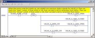
the MAIN IDEA is this ... the combination of the XIC (for the cycle) and the following ONS can be read this way in English:

when the cycle FIRST COMES ON ...

in contrast, just using the XIC would result in this translation:

WHILE the cycle IS ON ...

note the difference in the time/tense of the statements ...

once you get that “tense” part nailed down, then WHAT you need to do at the output end of the rung is usually not so complicated ...

but ... read on to the next post ... I think that what you’re ASKING FOR might not be exactly what you need ...

OPEN_CLOSED.JPG
 
the biggest question in my mind is this:

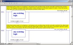
just WHAT in your program is already/presently controlling those two valves? ... probably it’s some existing logic which already works fine ... if that is the case, then probably all that you need to do is “bypass” that existing logic with a TRUE condition while the pump cycle is in progress ...

look at it this way ...

suppose that VALVE_A happens to be CLOSED at the instant that the pump cycle is started ... suppose that you “remember” that CLOSED state (by latching a bit, etc.) ... now while the pump cycle is in progress, you’ve got to OPEN VALVE_A ... suppose that you do that ... now suppose that WHILE the pump cycle is in progress, the normal/existing/previous logic for VALVE_A “changes” to cause an OPEN state ... no problem (yet) because your “bypass” will still keep the valve open – just like you want ...

but ...

now suppose that the pump cycle ends ... here’s the tricky part ... do you REALLY want the VALVE to resume its original CLOSED state (the state that you “remembered”) – or do you want the normal/existing logic to resume its own control over the valve? ... (in which case, the valve will remain OPEN) ...

IF (big IF) you decide that you do indeed want the valve to go back to its “remembered” state (the state that you “latched”) then the next question becomes when (if ever) does the existing/original/previous logic ever resume control? ...

here’s my best guess based on what you’ve posted so far ... you probably just want to “override” any existing logic for your two valves WHILE the pump cycle is in progress ... but ... just as soon as the pump cycle is over, you probably want the original/existing logic to “resume” its normal control of the valve ... that control MAY – or may NOT – put the valve back in exactly the same state that it was in at the beginning of the pump cycle – but the existing logic still needs to resume its control of the valve ...

am I even close? ...

next questions:

(1) is the “start pump cycle” signal from the HMI a momentary signal – or will it be maintained ON throughout the pump cycle? ...

(2) should the operator be allowed to interrupt/cancel/stop the 3 hour pump cycle once it’s been started? ... if so, how? ...

(3) suppose that the power fails during the 3 hour pump cycle ... do you want to “finish up” the remainder of the cycle once the power has been restored – or just “cancel it out” until the operator reinitiates it with another start signal? ...

(4) do the valves require a constant “OPEN” signal in order to remain open – or will they just stay where they’ve been driven once the “OPEN” signal has been removed? ... (along these lines, what did you mean by your reference to “open/closed/STOP commands”?) ...

(5) suppose that the operator pushes the START button again WHILE the pump cycle is already in progress ... usually we don’t want to start another cycle – or “reset” the existing cycle back to zero – but you need to think that through and write the program according to your requirements ...

(6) suppose that a pump cycle is already in progress – and one of the “VALVE OPEN” input signals fails (either due to a malfunction or maybe the valve actually doesn’t stay open) ... what do you want to do with the cycle in that case? ... cancel it? ... pause it? ... ? ...

hope this helps ... give me a call if you like ... once we get everything specified, the logic shouldn’t be too hard to do ...

naturally I’ve had to make some assumptions in the logic which follows - but I hope that you can see what I had in mind ...

OVERRIDE.JPG
 
Last edited:

Similar Topics

So I very much new to doing ladder coding I have a pump with a Stop float switch that stops the pump when a sump is low. I want my manual run mode...
Replies
13
Views
1,380
Hi, Complete novice on PLCs and need your help (again). On GT Designer3 what sort of button/switch do I need to add to Start/Stop a water pump...
Replies
7
Views
1,954
hello all, i am new here and to the plc: i have Studio 5000. i wanted to program an oil pump: i am using a low-level and a high-level sensor...
Replies
4
Views
1,897
I have a project to do. I'm required to design a pump controller. I have two pumps, one pump is on duty(active) and the other is on...
Replies
9
Views
2,654
Hello I have logic for two pumps that run based on levels and alternate upon each run. The issue is that I can not seem to figure how to go...
Replies
5
Views
2,993
Back
Top Bottom