PID development 2 ingredients (1 Solid, 1 Liquid)

Mike Lewallen

Member
Join Date
Jun 2009
Location
Ohio
Posts
6
I am looking for some help developing PID loops in a PLC
The PLC is TI505 family. I have Tisoft & Workshop. I've created simple heating loops in the PLC many times, but I have no idea how to attach the following problem.

I have been challenged to fill a tank with 2 ingredients (1 solid and 1 liquid)

System layout: A solid is screw feed into the end of the horizonal mixer. A liquid is pumped into the same end of the horizonal mixer. The mixture then falls out (gravity) the other end of the mixer into a holding tank. The screw (solid) is on a Siemens MM440 drive and the pump (liquid) is also on a MM440 drive. Both the screw and the pump outputs are the equation of a straigt line (they are linear). The holding tank is on load cells so I alway know the level.

I want to accomplish 2 things.

1) I know I must add 65% solid and 35% liquid. I want to use a PID loop to feed both the liquid and solid into the holding tank (thru the mixer). The "fuller" the tank the slower the addition. The "emptier" the holding tank the faster the screw and pump will run. I'm trying to make long batches.

2) The holding tank has a circulation loop with a nuclear density guage. So I always have a density solid vs liquid feedback. I know I want to maintain 65% solid and figured I would use a PID loop to bump the speed of the pump up or down to maintain the 65% solid.

So 2 things would influence the speed of the pump (1 being level of the holding tank and the other the feedback from the density guage).

Should I use a PID loop and somehow apply it to the curve (straight line) of both the pump and the screw?

Any help would be appreciated. Sorry for the bad spelling!
 
If I understood well,
you have two goals to achieve:
1. To maintain 65% of solid. Since solid and liquid is mixed up in horizontal mixer, there you'll need to control either one or both variables: pump speed for liquid and/or screw speed for solid.
2. You need to maintain level in holding tank around some desired value.

I would try to estimate if sufficent ratio solid/liquid can be achieved with controlling only one varibale (for example pump speed). If that is so, you'll have one PID loop for controlling ratio solid/liquid.
Other PID loop could be used to maintan level in holding tank in desired range, or if these proportions are known you could try to increase both (pump and screw) speed for some fixed amount depending on the level (Something like lookup table).

In my opinion first step would be to try to make PID loop working correctly to maintan desired ratio.
Once, I have seen similar application, where PID loop maintained ratio by controlling only one ingredient (let's saz pump speed for liquid). Then if level is too low, screw speed would be increased for some fixed value. That would be a disturbance for PID loop maintaining ratio. Since screw speed is increased, PID controller would increase pump speed to achieve new steady state (keep balance).
I'm not sure if this solution would work for you, but this can be done if tolerance set for ratio is not too tight. This way PID controller would fight external disturbance. Ofcourse, level information can be transfered to PID loop for ratio as feedforward signal.

I guess you'll need to perform additional tests to see how ratio solid/liquid can be achieved easily.

Do a search for ratio control, here's one quick example:
http://www.jashaw.com/pid/ratio.html
As you can see ration is maintained by manipulating onlyone actuator.
 
Last edited:
Mike, there is another idea. That is to use two PID loops.
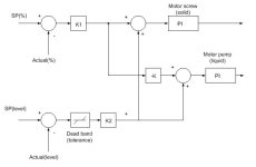
Idea is shown in the attachment. You normally use PI controllers (D is usually not needed in such application). First you set up PI(D) controller to speed up motors if input signal to controller is positive (error signal >0). That is only for simplicity of explanation.
First, let's say that level is normal. In that case level error is zero, so there is no factor added from level difference.
There is only error signal produces as difference SP(ratio %)-PV(ratio %). This is multiplied with some constant K1 and lead to PI controller to screw and with opposite sign to pump. If error is >0 (SP is higher that actual %) positive error value to screw PI controller will increase speed of solid, and with opposite sign, it will decrease pump's speed to find balance (error = 0).

If ratio is accomplished and level goes beyond tolerable limit, new error signal is formed. If SP (level) i grater than actual level, error signal is >0, so screw motor will speed up, but at the same time, pump speed will increase too.

This works in theory and I don't see a reason why this wouldn't work in practice. I guess it is now up to actuators (pump and screw motor)if this can be controlled in such way.
You have PI parameters but also K1, K2 and K (additional freedom) in tuning this application. This will not be easy, but I think it is possible. Just start from small gains.

Please, keep us informed.

Two_loops.JPG
 
First of all i don't know so much of PID, but short question since i find this post intresting. I see them very often, only difference is that the feedings are also on weighing.
But wouldn't it be easier to control with the density 1 component and with the level the other?
I think they would balance each other automaticly that way, don't you?
 
Thim,
I suggested two ways. Do you ask if it would be easier to have one loop for density and other for level?
Please, keep in mind actuators. How would you control density (% of solid)? You can do it by manipulating only one variable, or by two. In any case, how would you control level? You have same actuators that are already controlling density. You need to pay special attention not to make a state in which one controller would introduce permanent disturbance to the other.
If he knows relationship between level ans speed of motor drives, that one loop can be omitted but not sure if this is known for sure. With two loops approach, controllers will make action if there is either error in density or error on level.
First approach would be easier if density can be controlled by pump's speed for example.
I guess Mike is the one to ask.
 
I think this is too complicated - you are trying to do too much in one step.
If possible I would control on weight ie mass alone. Dump in X mass of component A and dump in Y mass of B and then mix up. This assumes that you can do this and they are not going to do a chemical reaction at any stage during mixing.

Dan Bentler
 
Pandiani, your 2nd idea, I'm a little confused with the diagram. The SP(%) & Act(%) are going into a PI loop and the output is taken * K1? And likewise the SP(level) & Act (level) and going into a 2nd PI loop and the output is taken * k2? And then both are added together for the SPEED REFERENCE to the screw? I think it is the "PI" in the box to the right that started my confusion.
 
PI is actually PI (proportional-integral) controller. Besides that I have put more gain constants intentionally to have more freedom in tuning. Since you have two actuators, idea is to make them both work to the same goal. You can change density by adjusting one variable or two at the same time. Here, loops are not separated (one for density, other for loop), you must consider them as one control system. I think that logic is not too complex. You set up desired density (SP%), then form error signal comparing to Actual densitiy (%). This is going to the PI controller of screw motor and with opposite sign (scaled) to pump.
The best way to understand this structure is to consider that level is within allowed limits (dead band output block is zero) and analyze how loop will work.
Then, assume that density is achieved so its error is zero. Now analyze how level discrepancy will affect control loop.

In steady state both errors will be around zero. If suddenly level is changed then, there will be a small correction factor (level error) signal that will influence both screw motor and pump.
Take your time and analyze this structure, it's not too complicated, I hope.

Regards,
Pandiani
 
Bill,
do you have any experience with fuzzy logic?
If you do have any examples that could simplify this, please post, so we can discuss them.

Thanks
 
I don't understand the problem,

Controlling two pumps to run at a fixed ratio should be easy. Changing the speeds of the pumps as the level increases is easy too. The only part that makes this hard is if the amount of material pumped or added is not proportional to the speed of the pump and/or screw. That is KEY!
The water pump better be a fixed displacement type so the flow will be constant and not vary with pressure.

However, Mike has hinted that the rate of material added is not proportional to the pump or screw speed. In this case I would run the water pump at a rate as a function of level. I would then gear the solid screw to the water pump. If the density reading drops then I would increase the gear ratio of the solid screw to the water pump.

This should be easy. However there are three PIDs. For the water pump and screw and one for maintaining the density ratio. The speed adjustments should be very slight.

Note if there isn't perfect mixing then the density sensor may provide poor results and phase delay. Adjust the gear ratio between the motor screw and the water pump should be done slowly with caution. It is all a matter of what do you trust the most.

I could do this in no time with a two axis controller.
 
Last edited:
Another thing you need to decide is what is more important to you; level or density. If you are at the right level but your density is wrong, what do you do? Also, you effective corection gain changes with level no matter what control concept you use. You can very quickly affect density of an empty vessel but it will take a much more aggressive correction to affect the density of a full tank. Which leads right back to the first point; can you go over level to get the right density.

You definitely want to 'gear' the two axes together. You should know your process well enough that you can come up with a 'perfect ratio' of solid and liquid to get the density you want. Level control will affect both axes through the established ratio. You can even do long-term ratio trim based on density if you want but that should be long-term (multiple batches). The per-batch corrections will be offsets to the axis speeds. Modifying the ratio between the axes to make this instantaneous correction gets kind of touchy as the vessel gets full since you are moving less and less material as the vessel fills. Offsetting both axes opposite ways, as Pandiani suggests, would provide the fastest correction. Just remember that the correction gain is dependent on the tank level and that is dynamic.

Keith
 
Another thing you need to decide is what is more important to you; level or density.
This shouldn't be a problem if the errors aren't kept smaller af the level SP is approached.

My gut is that this is an established process and Mike has not been told the whole story.

The whole idea of approaching the level SP slower and slower leads me to believe that someone has done this process before and knows that large density errors can't be corrected when the level can't change.

The fact there is a density meter leads me to believe that someone knows that there isn't perfect mixing or that they don't have faith that the mass delivered by the motors is constant for a constant speed.

I still think this is easy but nothing has been said about how long it takes for the density sensor to respond to changes in density. However, this is another good reason to go slowly as the level SP is approached.

Mike now knows the proper questions to ask.
 
I understood that density is more important than level. That is why I placed dead band block on level error. Peter is right, density sensor is crucial. Important thing is place where density sensor is mounted. Anyway, I think that Mike must supply more information if he wants more detail advice.
 

Similar Topics

Hi, I would like to assemble a simulator/practice booster pump system that uses PID to maintain steady water pressure under various outlet demands...
Replies
0
Views
60
Hello, I have a motor that we are sending a RPM Speed Output from 0-100% to the VFD. However, the Motor HP needs to be limited to 6000 HP and the...
Replies
3
Views
87
I have S7 1512C controler for controlling 48 PID temperature loop, the output is PWM. Please I need the best, most efficient way to write the...
Replies
13
Views
600
Hi all, I'm having trouble solving a problem I've been working on for several months, and thought you might like a stab at it. The machine runs...
Replies
22
Views
940
How can I connect PID Output to a valve. In ladder logic program is there any logic do I want to add between valve and PID? PV=SP What will be the...
Replies
7
Views
411
Back
Top Bottom