STEP 7 LITE Need help for a ladder diagram.

woosi

Member
Join Date
Jun 2009
Location
Athens
Posts
11
I need to build a ladder diagram for the following circuit:


Can some one help me please?I have downloaded STep 7 lite and reading pdfs about ladder design.

The projects purpose is the following:

We have a warehouse with 2 entrances as shown down below.One for entrance the other for exit.

There is a photocell in the first entrance that detects the incoming truck and turns the trafic light to red so the next truck knows that it has to wait.Also it gives signal to a counter so that the number of trucks entering the warehouse can be limited and monitored!
Then at the exit an other photocell detects the outgoing truck and gives a signal to trafic light to go to Green so the next truck can enter!
The green must be lit when truck is gone so the 2 photocells dont go on together
If the 2 photocells are On together there is an emergency motor door that closes and the red light is lit again.
 
Last edited:
In your original post you stated you have downloaded Step 7 Lite. The file you have posted is a Step 7 Micro/WIN file. This puzzles me, because the first software is intended for S7-300 and the latter for S7-200. Because these two families have almost nothing in common, I'm hesitant to give any answers because I'm afraid to send you in to the bushes.

Furthermore, the picture you have attached to your original post looks to me as if it was derived from a Siemens Logo! which is yet another completely different cup of tea.

Please elaborate.

Kind regards,
 
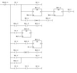
Attached is the LD equivalent which should get u started.

M100.0 is always off
M0.4 is counter pulses ( u need to figure this)
M29.0 is timer pulses.

Give a try to this and do tell if it works:D

LD1.JPG
 
In your original post you stated you have downloaded Step 7 Lite. The file you have posted is a Step 7 Micro/WIN file. This puzzles me, because the first software is intended for S7-300 and the latter for S7-200. Because these two families have almost nothing in common, I'm hesitant to give any answers because I'm afraid to send you in to the bushes.

Furthermore, the picture you have attached to your original post looks to me as if it was derived from a Siemens Logo! which is yet another completely different cup of tea.

Please elaborate.

Kind regards,

My teacher told me to build the circuit in Alpha programmer of Mitsubishi cause its easy and then use STEP 7 to transfer the circuit in LADDER diagram so i can upload the ladder diagram on a s7200 plc we have in our laboratory!
 
Next time, in your first post. TELL ITS HOMEWORK, and SHOW WHAT YOU HAVE DONE YOURSELF.

So what you need is step7 microwin. not step7 lite. Very different things.
 
@ Man meet.

My ladder diagram looks alot like yours.

For the counter i used a down counter with Ld:i0.1
CD:i0.2 and pv: the number i want to count down to zero.

i also used a lPl connection for the pulse i need to activate the final SR.

Can you see the file i uploaded?

Thank you alot for your time.Both of you.

Regards

Nick
 
Next time, in your first post. TELL ITS HOMEWORK, and SHOW WHAT YOU HAVE DONE YOURSELF.

So what you need is step7 microwin. not step7 lite. Very different things.

You are right and i am sorry for the confusion.
I was looking for lite and then i found the Step 7 micro and working on this program for my ladder diagram for s7-200 plc.


This is my final LD diagram.

C1 is the counter output that when counter reaches 0 then c1 goes to 1 and the system goes to a halt.

The lPl is the right symbol i need (i think) for a pulse signal for the SR number 4 so when the 2 inputs I0.1 +I0.2 go on together the safe mechanism is activated and the roll bar is lowered so the incoming truck stops at the entrance.

So what do you think?

Thank you again.
 
Combo whats Lego programming??
Using ready made programming blocks and combining these till you reach the solution you're after, even if it looks a little square at the edges?(y)

I think there's a typo involved and it should be logo programming.

Kind regards,
 
:)

Playing with the lego blocks, kids do that :).

http://www.lego.com

:)


A collegue of mine in a previous company where I worked for allways programmed in lego style, trying until he had what he needed. Is this really programming ? Mostly electricians who are beginning to use PLC's do that. Bin there 7 years ago. Some are trying the other languages, some are never changing bad habbits.


Using ready made programming blocks and combining these till you reach the solution you're after, even if it looks a little square at the edges?(y)

I think there's a typo involved and it should be logo programming.

Kind regards,
 

Similar Topics

Hi Guys, A customer of ours is looking to update an old Siemens PLC they have running one of there machines. They were able to provide us with a...
Replies
7
Views
1,979
Good Day Guys, Just want to know if its possible for me to open a Simatic S7 project in Step 7 Lite?? Thanks and more Power... 🍻
Replies
3
Views
3,837
Hi everyone CAN SOMEONE EXPLAIN THE FUNCTION OF THE SYMBOL TABLE AND FLOW CHARTS.ON A PLC. Thanks James
Replies
2
Views
1,561
Hi, I am brand new with Siemens 300 series.I did little work with 200 series using Microwin software.My main problem is that I was given a small...
Replies
50
Views
21,908
Hie there.I am new to Step 7 Lite and I have two questions. 1.What purpose is served by instance DBs linked to FBs? 2.The manual I have does not...
Replies
2
Views
1,647
Back
Top Bottom