one more PICO question

best49erfan

Member
Join Date
Aug 2003
Location
Titusville FL
Posts
70
I was reading the getting results manual and it talks about having the memory module. Do you have to have that to retain the program in the Pico or will it lose the program after every powerdown?
 
well i couldnt find a cord to use to power it up. I found one a little bit ago.....a spare PC power cord..... It has retained the time so im sure it would retain the logic.
 
Memory module plugs into com port. So when you turn it on it will look to its own eeprom for a program or if you want it to, it can look to the com port, where it will see either your PC with a new program or your memory module with an alternate program This can be handy if you want it to do different things. I had one where after power on it looked to com port, saw nothing plugged in, so started with blank program. Just had to tell it to look to its own eeprom and its OK. Will retain program for ever, and some with Real Time clock will retain timers and counters.
 
well i couldnt find a cord to use to power it up. I found one a little bit ago.....a spare PC power cord.....

After you cut the pc cord end off did you determine
what wire was L1,L2 and Gnd. ??
Be Careful... :cool:
 
Gnd should be easy...are L1 and L2 specific? ..ie is L1 the hot and L2 the neutral or vice versa?

Does it matter? Green is ground and should be specific, unless the neutral is bonded at the plc (which is unlikely) then L1 and L2 probably wont matter how is connected.

Does it matter?
 
rsdoran said:
Does it matter? Green is ground and should be specific, unless the neutral is bonded at the plc (which is unlikely) then L1 and L2 probably wont matter how is connected.

Does it matter?

Good point Ron. Let's visit this topic...

A quick look at the specs for an AC powered PICO and I see that, like most stuff these days, it will accept a 90-264VAC supply.

OK, so it shouldn't matter which terminal gets the 'hot' lead, because if I connect 240V to it, both leads are considered 'hot'. If I were running it on 120V, I think most of us would connect the 'hot' to L1, and the 'neutral' to L2. If for no other reason than 'common practice'.

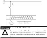
But wait! Look at the 'Connecting Incoming Power' section of the manual and you find this:
[attachment]
The PC Cable Socket is at the potential of L2???? Are they saying that if I connect it to a 240V supply where neither leg is grounded, I'm gonna go on my a$$ if I accidentally touch one of the pins of the PC cable? Or possibly fry my laptop?

What is the purpose of bonding the PC cable socket to one of the incoming power terminals? The fact that it's "documented in the manual" is no excuse for lack of isolation... :rolleyes:

Your thoughts?

beerchug

-Eric

pico.jpg
 
My opinion-

Eric Nelson said:
Your thoughts?


I think this is pretty much a statement telling you make sure L2 is grounded, whatever the voltage..

I have never dealt with a 240V industrial control system, but I would think that if 240V is needed, You would find a "no nuetral" control transformer with one of the leads grounded. I don't see any reason to use 240/120 from the same transformer. You would have to worry about load balancing and you would have 2 "hots".

If I had a project that required both 120 and 240, I would have 2 seperate transformers. One for the 120 and one for the 240.
 
240 is not very common for any use. I have personnally never seen it used for control circuits..... I have seen 480 used, but that was a misunderstanding between the company and the manufacturer of the panels.
 
More Thoughts

My guess is that the 90-264 VAC rating is not to accommodate the odd person in North America who may want to power the Pico from 240 volts but to accommodate the majority of the world outside North America where 220 volts is the standard.

My understanding is that the 220 volt single phase voltage is usually 1 phase of a 380 volt, Y connected 3 phase system. These systems usually have the star point (neutral) grounded, which would mean that one line of the 220 volt would be grounded.

The warning is there to tell the installer to be sure to connect the grounded line to L2 and if neither line is grounded, be careful. I don't condone this but I guess you get what you pay for.
 
Now we getting to the heart of the matter

First, if you havent dealt with 480/240 volt control then you havent done much control work...IMO

Following european standards many systems use 380 volt for motors etc but 240vac is standard for control voltage. Note: we in the US have not had to follow the European methods for long. We also have used 220/240 vac for control work.

I asked that question specifically to see the responses.

Lets IGNORE the fact that 240vac was used and replace it with 120vac. In many cases when using a "control" transformer neither terminal is bonded to ground....this means that when measuring either TAP to ground you will see 1/2 of the supplied voltage, thats the main reason for connecting one leg to ground...it supplies a reference that is relevant to ground potential.

AB has a tendency to do wierd things with its products some times.

The statement/questions triggered my response
 
Actually, I have done plenty of control work. The standard for control voltages are usually 24 vdc or 120 vac. This is to minimize voltages exposed to operators, especially the ones who think they know what they are doing when they open panels to reset items they have no clue about.
 
Re: Now we getting to the heart of the matter

First I agree with best49erfan. 480V or 240V for control power is not common in the US. 24VDC and 120VAC are the most common.

rsdoran said:
In many cases when using a "control" transformer neither terminal is bonded to ground....

Many cases? When I get a new piece of equipment, it's in our spec, and if one leg of the control power isn't grounded, it will be before the equipment builder gets full payment. I would expect it to be more like a "rare case".

rsdoran said:
this means that when measuring either TAP to ground you will see 1/2 of the supplied voltage, thats the main reason for connecting one leg to ground...it supplies a reference that is relevant to ground potential.

1/2 of the supplied voltage?
Theoretically you should see 0V. But, in reality, you could see anywhere from 0V to the full voltage in an ungrounded system.
 
I have dealt with this for many years, the last place had several gravure presses made in Italy (circa 1970 give or take a few yrs). These used 120vac control tranformers with neither tap bonded to ground, if you measure between ground and either tap the reading is usually around 57vac (this may vary a little).

I have worked with all kinds of machines from all over the world. I have seen and still see machines that use 240 and/or 480 for control voltage. I dont even like 120vac for control, I would prefer it was always 24vdc. The facts are that many European and American companies wired things using whatever source voltage as control voltage, I guess it saved on buying transformers. The practice of using 24vdc for control is relatively young. Its a good practice in my opinion.

Then again I have an Electricians Handbook thats old, very old and one of the first things it shows is a motor control circuit using supply voltage...similar to this
stopstartmotor.gif


I should get a new Handbook, this one has polyphase and vacuum tubes in it. Its been a good book, my bible in a sense. Its not necessarily a good book to learn with though. The main reason I havent bought a new one is it hasnt changed that much ...still has polyphase and some poor references to communication frequencies etc. When I started doing this stuff alot of that was new technology. I think I have one of the last issues before the original author died.

What is common depends on your reference in time. Over the whole period that machines have run on electricity? 120vac nor 24vdc were common. Over the last 25 years or so yes 120vac was but 24vdc is relatively young.
 

Similar Topics

Hello, i need to use P_Intlk and feed the Status interlock OK bit to a P_DOut block. However, there's 17 interlocks for this output. How can I...
Replies
1
Views
102
Hi everyone, recently i worked with a cmore panel and have the question that how can clear alarm list whit remote form,right now only can with...
Replies
0
Views
103
Hello, friends, I am trying to upgrade a system that uses an Onrom incremental encoder (E6B2-CWZ6C) connected to a Danfoss VFD (FC360), but now...
Replies
4
Views
267
Hello Friends I have took the sample program from AB webpage and modified, but I can only send 127 chars...
Replies
1
Views
176
Hello, I am new here and have been working with PLCs for a few years now. I have been tasked with setting up a Micrologix 1400….. to a Cmore 10...
Replies
10
Views
478
Back
Top Bottom