Mitsi Ethernet Set-Up for A-Series CPU

craig_avanzar

Member
Join Date
Sep 2007
Location
san antonio, texas
Posts
151
Hello again.:D

I am attempting to set up ethernet coms to an A series Mitsi processor.

Processor is A1SJH/ Ethernet card is A1SJ71E71N3-T

This is a static address that I will use only to monitor and occasionally tweak the program as needed.

While reading the manual I got confused on the ladder diagram example provided.
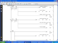
It starts with an initial pulse, some input not being true then a DMOV of the IP address in Hex to register D100. Got that part. But then there is a branch below it

[TO H0 K0 D100 K2] that I don't understand and then there is another branch below that where they SET an output Y19 and call it the initial request.

My first thought is that I only need to set the IP address, have the Mode setting to zero and all of the dip switches to off. This is running equipment so there is not a lot of play time for trial and error and I'm not real confident. I know that when I set up the analog card in an FX processor it was pretty straight forward but...Murphy is always hanging around.

I've attached a screen shot of the code from the manual.

Any help would greatly appreciated.

AS ALWAYS THANKS FOR YOUR TIME.:site:
untitled.jpg
 
Ethernet card (like everything else other than plain digital input and output cards) is so called special card. it means it has it's own processor and to make it work for you, first you have to write program that will configure it, handshake with it etc.
this is done through mapped I/O that fit in standard I/O range (X and Y) and by directly accessing part of card's memory. This memory that is accessible by PLC CPU is called buffer and the basic I/O is for essential handshaking (module error, module ready, initialize module etc.).
to read and write to and from buffer, you need to use TO and FROM instructions.
arguments of those instructions include things like:
- an address of the card (because in a modular plc, there can be several different ones)
- buffer number (actually number of FIRST buffer you want to access, because you can access more than one)
- PLC memory location (from which you read or to which you write)
- amount of data transferred (number of 16-bit words to be transferred)

once you load module with required parameters you issue init to tell module it's ok to use those settings. check download section for instruction manual (and ethernet)
 
[TO H0 K0 D100 K2] = write 'TO' to start address of ethernet module hex 'H0' 1st slot next to cpu, buffer address 'K0'of ethernet module, the value in register 'D100 & D101' where 'K2' means 2 words. The ethernet module is a 32 point module in slot'0' therefore I/O addresses = X0-XF & Y0-YF (32 points) read the manual and you will find what these I/O addresses represent in the module
 
"read the manual and you will find what these I/O addresses represent in the module"

Which manual. I have worn out a pair of glasses trying to find this information. I have gone to the downloads section and only find a hardware manual. I have looked in the A series manual as well as the GX Developer manual. Then tech support had me download the manual that I got the screen shot from and I cannot find a reference to any I/O or buffer area attributed to this module. I will continue looking but if you have the time, I realize you are busy and I do appreciate everything so far, could you please point me at the manual that has this information.🤞🏻

AS ALWAYS, THANK YOU FOR YOUR TIME.
 
📚 I am still reading but I have discovered the table that has all of the I/O on it and then I looked at one of the programs that uses CC-Link and the light came on. They used connection one for the cc-link so I'll use connection two for the ethernet connection. The program example in my initial post is using UDP and I will be using TCP/IP. I plan on writing the code and possibly posting it here for feed back.

At least thats the plan....o_O
 
when you need info on mitsubsihi product, just got to www.meau.com,
download, manuals and use any of the three search forms.

also when you buy mitsubishi product such as ethernet card etc.
it comes with small page (or booklet in some cases). check it out.
this is hardware manual only but it will have references to relevant manuals.

i don't have access anymore to old projects (A series has been around for long time)
so i can't give you code sample. there is code sample in the manual
(much bigger than what you need) that will get you up and running.

there is also downlaod section on mrplc.com.
 
Craig our company is a Mitsubishi distributor in Australia, and thus we know where to look & have access to top end Tech support & the latest equipment before it is released & Mitsubishi training.
Glad to help.
 

Similar Topics

hi all regarding : mitsi q series ethernet qj71e71-100. there's an old coax network at a client's chicken factory that's fallen over. it...
Replies
9
Views
1,926
Hi, I have two systems each consisting of a Q03UDE connected to a Beijer E1070 all over Ethernet... I would like to share some REAL's over the...
Replies
5
Views
3,826
Hi Scenario is a Mitsi PLC which is connected to an E- Terminal using a CPU direct serial cable. I have been told that i can use transparent...
Replies
0
Views
2,506
Hi, I have been asked to add a module to an existing PLC, which has a processor Q2AS(H). I have looked online and found A1SJ71QE71N-B2 and...
Replies
2
Views
1,780
Mitsi Q - Ethernet - anyone know how to read bits using 'readup' instruction? (GX IEC DEveloper) Tried using k4M100 format in place of D register...
Replies
2
Views
2,321
Back
Top Bottom