Trying to learn S7 400 and Profibus

geniusintraining

Lifetime Supporting Member + Moderator
Join Date
Jun 2005
Location
SC
Posts
8,274
I have a S7 416 2DP and I am trying to get it to communicate to a 200.

I guess anyone have any links so I can read the setup, I have my 5512 plugged into X1 on the 416, then a straight cable running from X3 to the Profibus port on the 200

Should I be able to plug into X1 and see my 200 when I access the nodes in Step7 ?

The red led (EXTF) is solid on the 416, the INTF and BUSF are both off

Do I need to configure it? one of the messages is no other nodes found, but since this is part of the CPU and not a separate module I thought it may not need to be configured... and I can not find where to configure it.

I do not have a program in either CPU, I am also not showing any errors in the 400 stack

Like I said I am just trying to learn... thanks for the help :)
 
The master (400) would need the Profibus network programmed into its hardware profile.

Both addresses will also need setting in respective hardware profiles (although unsure of 200's never used them).

If only 2 plugs, both would need the resistor on.
 
Hello GiT.

I also have zero experience with S7-200, but can say so much:

"Should I be able to plug into X1 and see my 200 when I access the nodes in Step7 ?"
I think not. Maybe if you you have "routing" all setup and running. But to begin with for sure no.
edit: If the S7-200 is correctly setup as slave to the 416-2DP, then you should be able to see it if you hook your PC on the DP master port. However, you are not ready for this yet.

"The red led (EXTF) is solid on the 416, the INTF and BUSF are both off
Do I need to configure it? one of the messages is no other nodes found, but since this is part of the CPU and not a separate module I thought it may not need to be configured... and I can not find where to configure it."
At least the port in question (X2 ? There is no X3 on a 416-2DP) must be setup as DP Master. See below.

"I am also not showing any errors in the 400 stack"
This is worrying. If there is a red EXTF, then there must be entries in the diagnostics buffer.

For the S7-200 to be recognized as a slave to the S7-400, you have to:
Setup a port on the S7-400 CPU as DP master.
Import the GSD file for the S7-200 (CPU 215-2 DP) into the HW Catalog of STEP7. It will be added as "CPU215-DP" to the folder "Additional field devices" in the HW Catalog.
Add the "CPU215-DP" to the DP network of the Master.
Specify a DP station address of the new slave.
Setup i/o data for the Dp slave node.
That should be the procedure for the S7-400.

Not sure if this FAQ is helpful or not:
http://support.automation.siemens.com/WW/view/en/264764

For the S7-200, there is some information from page 438 and onwards in this manual:
http://support.automation.siemens.com/WW/view/en/1109582
I hope it helps you enough.


edit: I just noticed that the manual refers to EM277 as the DP slave module.
And there is a GSD file called "EM277". Not sure what the big difference is between this and the "215-2 DP". Maybe you should use this GSD file in stead.
That just shows how much I know about S7-200.

edit again: In the current HW Catalog under "SIMATIC", there are already entries for CPU 215-2DP and CP242-8.
If your S7-200 is any of those, then you dont need to import GSD files.
 
Last edited:
Hi Guy's

Thank you both... I will try and read up some on it, the communication is the hardest thing for me to understand so when I have time I like to play with it.

Like I said I don't really have a use for it but just wanted to see how it worked.


(X2 ? There is no X3 on a 416-2DP)

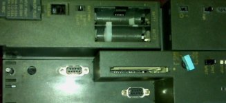
For some reason it has a 9pin with X1 and another with X3, not sure what happened to X2?? I can take a picture if you would like, I just thought it was something I was missing (did not want to show my ignorance :oops: )

Thanks again
Mark (GiT)
 
If you look in the HW Config in STEP7, the two available ports are called X1 and X2. Siemens is usually pretty good at getting these things right. If they made a mistake, or I made a mistake, I would like to know. Pictures are always nice.
 
On the PLC itself... X1 and X3 (misprint?)

I have not had a lot of time... but maybe no error in the stack because I do not have them configured yet?? just a guess..

I hope over the holiday I will get some time.

Also not a very good picture (it was from my phone), but the one on the right is X3 the other is X1

IMG00027.jpg
 
Hello
I am note sure what is your CPU S7-416 and wnich profibus modul you use in S7-200.
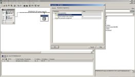
I have attached a example projectView attachment S7-416_s.zip and a pictureHW_Config.jpg of HW config of S7-400,
On picture is shown where you enter the VB adress in S7-200, where S7-400 will write. You should change your

profibus address on S7-200 module (EM277 in this example)to 4 or change the HW config address in S7-400

Regards Mitko
 

Similar Topics

Hi all, Got a new device I'm trying to work out how to communicate with. It came along on Monday morning after 9 months of development inside my...
Replies
19
Views
5,672
I am a water treatment plant operator tring to learn as much as I can about programming. We use TSX plcs (Quantum)and program ladder logic using...
Replies
1
Views
1,594
I am very familiar with AB PLC 5 and SLC500, however we have recently added a new system that has a contrologix 5000 in it. Is there any where...
Replies
4
Views
1,815
Hello group, at work we predominately use PLC5's so the only software that I've worked with is logix5. We have a bunch of stand alone Automation...
Replies
11
Views
4,026
Hi everyone. I am trying to learn about PLC5/03's. I have set up an Inspiron 1100 laptop-->usb to serial port adaptor--> SLC 5/03 serial port. I...
Replies
1
Views
2,865
Back
Top Bottom