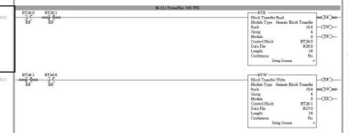
PLC5 Block Transfer Write RIO

wevie0037@

Member
Join Date
Jan 2007
Location
Iowa
Posts
16
Greetings,

I replaced a 1305 drive with a PF70 drive. The 1305 was controlled by a PLC5 via RIO using a 1203-GD1 Remote I/O Communications Module. The PF70 has a 20-COMM-R.

Of course, I had to swap some words around in the PLC5. The 1203 uses word 0 for logic and word 1 for speed reference. The 20-COMM-R is just the opposite.

The PLC5 had a MOV command to move the speed reference to word 1. I need to use a BTW to move the speed reference to word 0.

I must admit, this PLC5 is a little before my time, so bear with me please.

The word I need is O:044. That would be Rack 4, Group 4, Module 0, right? This is how I have the BTW configured using control block BT9:1 and the Data file is N27:0. N27:0 has the correct value, but O:044 does not. Changing N27:0 does not change O:044

What have I done wrong?
 
from the "probably overkill" department ...

let's concentrate on this statement first ...

The PLC5 had a MOV command to move the speed reference to word 1. I need to use a BTW to move the speed reference to word 0.

no offense intended, but you MIGHT be a little confused about what's going on here ...

secret handshake: technically a BTW doesn't move a value (example: a speed reference) to a WORD ... instead a BTW is used to move a "block" of several values (well, usually there's more than ONE value) FROM the PLC processor TO some other device (example: to a drive or an analog I/O module) ...

if I understand your problem, then my distinguished colleague OkiePC has probably nailed down the solution for you ... specifically, you probably need a (much simpler) MOV operation instead of a BTW ...

in simplest terms: if you want to put a certain value into O:044, then follow Okie's advice and use an MOV instruction – not a BTW ...

common source of confusion:

most drives (I haven't had time to research yours) use DISCRETE words to handle "quick" signals - things like the speed reference command – start the motor – stop the motor – run in reverse – and other "time critical" signals like that ... using addresses such as O:044 would make perfect sense for signals such as that – because those I/O Data Table type signals get transferred very quickly ...

on the other hand, there are many other signals (usually called "parameters") that don't need to be sent to the drive quite as fast ... things such as Accel Time – Decel Time – Current Limit – etc. ... signals like these are usually transferred TO the drive with Block Transfer Write instructions - and transferred FROM the drive with Block Transfer Read instructions ...

the "upside" of this arrangement is that the "block transfer" signals don't take up any room on the PLC processor's (limited size) Input and Output Data Tables ...

the "downside" is that signals communicated this way don't get transferred quite as fast as discrete (I/O Data Table) type signals ...

if what Okie posted doesn't completely take care of your problem, you might want to consider posting the part of your ladder program that controls this drive ...
 
Also you're mistaken on the word order....

The 20-COMM-R does not put the logic status/command bits in the BTR/BTW at all.

If you are using discrete I/O with 1/4 rack addressing then you have the following:

I:/O: Word 0 - Block Xfer Control, Word 1 - Logic/Status bits

BT: Word 0/1 - Speed Reference/Speed Feedback, Word 2/3 and so forth, Datalinks

If you are using 1/2 rack addressing then

I:/O: Word 0 - Block Xfer Control, Word 1 - Logic/Status bits, Word 2/3 Speed Reference/Speed Feedback

BT: Word 0/1 - Speed Reference/Speed Feedback (Again), Word 2/3 and so forth, Datalinks

So, to add to Okie and Ron's discussion, ONLY if you have configured the 20-Comm-R/PF70 as 1/2 rack will you be able to move the speed reference directly to an Output address. If you have 1/4 rack, then you WILL have to use the BTR/BTW to move the speed reference and read the speed feedback.
 
Last edited:
When the 1203-GD1/GK1 was used in "block transfer mode", it worked just like the 20-COMM-R does. RA just didn't give the 20-COMM-R the simpler discrete-only mode that the older module has.

Block Transfers can be between 1 and 64 words long. The I/O address you point them towards is the window through which they multiplex the data block. You won't see the 1-word value you are sending show up in O:044 because that memory location is part of the transfer process.

To verify that the block transfer instruction is successfully moving the value from N27:0, you will need to use the PowerFlex HIM module to monitor Parameter 272, Drive Reference Result.
 
Robert has it right:

I am just in the process of implementing this for four PF70 Drives on a PLC5/40.

20-COMM-R Manual:
http://literature.rockwellautomation.com/idc/groups/literature/documents/um/20comm-um004_-en-p.pdf

Have a look at that the Adapter set up in Chapter 2, pages 2-2 and 2-3. You have to decide if you are going with 1/4 or 1/2 Rack configuration. The Command and Status is always done with I/O. The Speed Reference and Feedback is done with Block Transfers for 1/4 Rack, and I/O for 1/2 Rack. Also look at the I/O images on pages 4-2 and 4-3. The Logic/Status words in Appendix D are handy too.

I had lots of I/O available, so I elected to go with the 1/2 Rack configuration. If you are tight for I/O space, you might want to go with the 1/4 Rack configuration. Two words as opposed to four words. The two words would be the same as the 1203-GD1, and you wouldn't have move any I/O around.

If you are In Support as AB likes to call it, there is a tech note for 1/4 Rack.

http://rockwellautomation.custhelp....tbl=9&p_id=45063&p_created=1192796086&p_olh=0

I hope that helps.

Stu......
 
Block Transfer Woes...

I'm trying to do this process now but I can't get the Block Transfer to work. No status bits (or anything else) appears in word 1 of the data. My VFD, on 20-comm-r in this example is rack 14, group 4, 1/4 rack. The configuration goes from "F" to no "F" in the channel configuration when I switch on the VFD power, so I am assuming I've got the 20-comm configured correctly. Likely missing something simple. Thanks!! RB
PS - The correct status bits are showing up in I:145. I'd use those but I need the datalinks, too.

SNAG-0235.jpg
 
Last edited:
I didn't use the Datalinks in my application, but my guess would be that most likely your problem is the Setup in the PowerFlex Drive, or the 20-COMM-R. All the Configuration is done there.

Is Parameter 12 in the 20-COMM-R set properly?

Are your Datalinks set in the VFD (PARAM 300-317)


Stu.....
 

Similar Topics

Hello, I am currently converting a project from PLC5 to ControlLogix. I have migrated the program from Logix5 to Logix5000 and any Block Transfer...
Replies
4
Views
3,328
I am replacing a PLC5 with a 1756-L73 and i am trying to reuse a 1771-DB Basic Module. I am leaving the PLC5 in the chassis setup as RIO adapter...
Replies
7
Views
5,104
Good day all. I had two mass flow control's good bad (not at the same time) and have now replaced them. The challenge I have is, where I'm...
Replies
16
Views
3,887
I am new to this field and it's been a while since school .. 10 years.. I am trying to find a plain english explanation of block transfer read /...
Replies
10
Views
9,278
Dear All, I have one PLC 5/20 that connected with industrial computer 1784-T36. The PLC5/20 consist are some DI, DO, Analog input, Analog output...
Replies
5
Views
9,399
Back
Top Bottom