Help - Micrologix 1100 Code not working as expected

timbo_uk

Member
Join Date
Nov 2005
Location
Bradford, UK
Posts
336
Hi there,

(Actually a continuation of this thread (http://www.plctalk.net/qanda/showthread.php?t=47163) but title not really getting attention.

I am trying to work out why this bit of code is not working as expected.

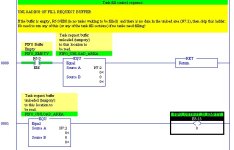
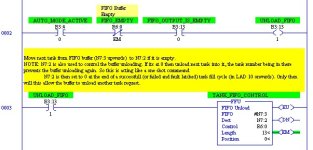
Basically I am trying to empty a FIFO buffer (numbers of tanks that need filling up) starting at N7:3 and 13 integers long into N7:2.

The trigger to unload is supposed to be when N7:2 is empty. The idea behind this is: tank requests to be filled, tank number is added to FIFO buffer, first request unloaded from buffer into N7:2, N7:2 is used to call the particular tanks fill subroutine, when finished that routine writes "0" into N7:2, it should then repeat the sequence.

The bit of code below never unloads the FIFO even when N7:2 is at zero.

By trial and error I have found I can make it work by adding a bit triggered from the free running clock (S4:12) onto rung 0001 between the EQU and the bit output. It works perfectly as expected then.

Can anyone see why this is? I am a bit of a novice self taught programmer, so not sure of the "nitty gritty" going on during the scan.

attachment.php

attachment.php


The full (work in progress) project can be downloaded from the end of the topic linked too at the top of this post.

Hopefully somebody can tell me why, and suggest ways around it o_O

Thanks

2009-09-23_051003.jpg 2009-09-23_051021.jpg
 
Hi,

Maybe I am wrong,

Your condition to return in rung zero is the same as request to unload [N7:2 =0], won't the scan returns to the calling routine in rung zero itself before it even scan the next line?

Edit:
oops, didn't notice the register empty condition.
 
Last edited:
Hi,

Maybe I am wrong,

Your condition to return in rung zero is the same as request to unload [N7:2 =0], won't the scan returns to the calling routine in rung zero itself before it even scan the next line?

Errr, just looked at it again and no. The first rung only returns if both the buffer is empty and the unload area (N7:2) is also empty. In otherwords, if every fill request has been fulfilled, so no need to even try to do any more.

As a side note, rungs 1,2 & 3 were originally one one rung, but I split it up to try and see why it didnt work :)
 
Last edited:
The bit of code below never unloads the FIFO even when N7:2 is at zero.

By trial and error I have found I can make it work by adding a bit triggered from the free running clock (S4:12) onto rung 0001 between the EQU and the bit output. It works perfectly as expected then.

Can anyone see why this is? I am a bit of a novice self taught programmer, so not sure of the "nitty gritty" going on during the scan.

Your description of adding a bit controlled by the free running clock tells me that the fifo only triggers on a false to true transition and the way you have it it sees that once only at first scan.

Try putting numbers in each of your N7:3 to N7:15 that make sense to you say 3 to 15, but make some of them the zero, you want as your test operation, you will, I hope see a two step operation when you systematically change the one, in I think N7:2 to zero, hopefully you will see the steps you want.
I think the false to true transition of the Fifi is the key.

Added
The other thing that could be happening if it does not need that true to false transition is that it unloads them all in 13 scans and you miss it, the numbers I mentioned earlier in N7;3 To N7:16 would show this
Maube you could move the clocks second value into say N7:15 in order to create a varying pattern.
 
Last edited:
Does the called routine set N7:2 back to zero on its first scan? If so then this bit of code would never see N7:2 go to non-zero then back again and not trigger the FIFO unload again.
 
Your description of adding a bit controlled by the free running clock tells me that the fifo only triggers on a false to true transition and the way you have it it sees that once only at first scan.

That's right. Get rid of that RETURN command, so the FFU can be executed with a false input and put the code back into one rung like you started with.
 
Brilliant :)
I knew you lot would point me in the right direction :site:

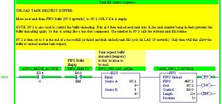
I have now altered the start of the ladder to this:

XIC B3:4/0 XIO R6:0/EM EQU N7:2 0 FFU #N7:3 N7:2 R6:0 13 1

And it works exactly as expected. So the FFU does only seem to trigger on a false to true transition (as I would expect). I think the problem was how the logic is left in a ladder after the RETURN instruction; I reckon that if the rung after the return was true, then the return command is triggered then the logic stays true, but is not scanned. Then when the logic was correct to scan it again there wasn't actually a false to true transition?

Maybe someone could clarify that?

Would any of you programming experts expect to normally see a return in some logic like I had it; or would it have been earlier (eg in LAD2) so that file was never actually called?

Cheers again!

2009-09-23_185054.jpg
 
I would only use a RETURN instruction to skip over some heavy math instructions that did not need to be executed at the moment. If you made the subroutine call conditional, you would run into the same problem you were having. A work around if you must re-trigger the FFU without using a false to true transition would be to reset the .EU bit after every execution.
 

Similar Topics

Hello Everyone, I am a college student at the University of Wisconsin-Platteville. My professor is having me integrate a Panelview 800 HMI into...
Replies
8
Views
6,872
Thanks for taking the time to read this. From a string I am receiving vis RS232, I'm trying to convert that to a REAL or Floating Point. I need...
Replies
8
Views
4,578
I'm a trying to do a project with a Micrologix 1100 Ser A for a school project. I know a little ladder logic, but haven't ever used AB PLCs. I...
Replies
24
Views
11,107
hi guys, im trying to make my vfd automatically adjust speed based on the liquid level of a tank. if the tank level keeps rising to speed up my...
Replies
16
Views
4,737
Hey, I have a Micrologix 1100 and I am sending 6 messages to a Yaskawa VFD, both reads and writes. I can't figure out how to build logic to have...
Replies
4
Views
1,704
Back
Top Bottom