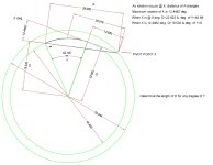
math used to calculate these dimensions

rocksalt

Member
Join Date
Aug 2008
Location
Texas
Posts
102
I am an old man who can't remember much when it comes to geometry.

I am trying to calculate the numbers on this diagram. I have drawn them in autocad, but need to get real numbers in my PLC.

As the object rotates between 0 and 12.4462 deg. Calculate the distance from the center of the circle to the intersecting line.

What would be the formula to generate these numbers?
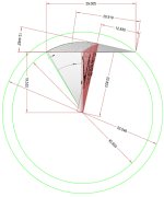
geo.jpg
 
avk8qs.jpg


hypotenuse C is the same for both triangles with right angles a & b formed by the ~12 deg rotation.

So you are looking for the distance a, poorly labeled as ad through bd, as the rotation occurs?

I'm probably older than you, rushing out the door, and I dont' remember which is which, but isn't the sine or cosine function the ratio of one side of a 'triangle' to the hypotenuse?

I'll think about it during the housewarming party I'm headed to.

Dan
 
Make is easy on us.

What would be the formula to generate these numbers?
What numnbers? I have no clue which one you know and which ones you need to calculate. Simplify your drawing to only those lines, angles and numbers you know and what ones when to be computed. At least in the last drawing you showed how you are measuring the angle. Get rid of the brown stuff if it isn't important. It clutters up the drawing.
 
Pete and all,

The brown lines represent the movement at 3 places, the beginning, middle, and end ( I forgot to add in the middle dimension of D!). I used this to try and show the different dimensions of D based on the dimension of A and rotation at X.

I converted this drawing to .jpg which sacrificed the ability to see the numbers in the original drawing.

Let me explain further.

A cylinder with a travel of 16.175" exists. This dimension is the brown lines 29.005-12.83=16.175.

12.83"(A) is 0" of cylinder travel which is 42.98deg.(Y) which is a D of 22.823"

29.005"(A) is 16.175" cylinder travel which is 0deg.(Y) which is a D of 19.532"

The "clutter" you see was only to help in understanding how this works mechanically.

This representation is for torque. As the cylinder moves, the moment arm changes in length over the course of 42.98 degrees.

If I want to calculate the force of the cylinder in relation to the center of the circle it will change dramatically (22088.4361 ft-lbs) (there are 2 cylinders doing the work over the course of the 42.98 degrees.

I have made the measurements at 43 points and entered them. This, of course, is not the way to do this.

D=inches
X is deg.
A is inches
Y is degrees
 
Last edited:
R0 is the inner radius 52.046/2
R1 is the outer radius 45.650/2
L1 is the distance between the tangent points on R0 and R1 = 12.830
P1 is the tangent point on the inner circle.
C is the center of the circle.
Z is the angle between the line from C to X and from C to P1.
Z = atan(L1/R0) or Z=acos(R0/R1) or Z=asin(L1/R0)
W is Y+Z
P2 is the point that moves on the inner circle.
L2 is the distance between X and L2.
Use the cosine law to compute L2
L2 = R1^2+R2^2-2*R1*R0*cos(W+Z)
Now use the law of sines to compute the angles of the triangle from C,X and P2.
sin(Y+W)/L2=sin(a2)/R1) where a2 is the angle between the vectors from P2 to X and P2 to C.
Now the distance from C to the line P2 to X is is easy to find. D=R0*sin(a2)
I will let you do the number crunching. I need to exercise while the sun is out.
 
There is an obvious error

L2 = sqrt(R1^2+R2^2-2*R1*R0*cos(W+Z));

The values I get don't quite match up with yours. There are some obvious errors in yours for instance should D be 1/2 45.65? Are you getting these dimensions from moving a mouse on a computer screen? If so then they aren't accurate because of the pixel resolution.

I get 19.63355 when y is 42.98 degrees.
ftp://www.deltamotion.com/peter/Maxima/RockSalt.html
 
Last edited:
I was given a drawing in .pdf with the numbers you see in the drawing. I re-drew it so I could understand what was going on then measured the lines. So the numbers are what was provided. I thought something was not right when the drawing indicates a 16.175" stroke when the cylinder is 16.0 actual measured. The actual measurements from autocad gave me:
degrees arm length 0 19.53239 1 19.65008 2 19.77431 3 19.8955 4 20.0149 5 20.13249 6 20.24824 7 20.36215 8 20.47147 9 20.58429 10 20.69249 11 20.79873 12 20.90299 13 21.00523 14 21.10544 15 21.20357 16 21.29959 17 21.39346 18 21.48515 19 21.57461 20 21.66179 21 21.74416 22 21.8116 23 21.90918 24 21.98673 25 22.06172 26 22.13406 27 22.20367 28 22.27047 29 22.33435 30 22.39521 31 22.45291 32 22.50731 33 22.55827 34 22.60561 35 22.64912 36 22.68858 37 22.72735 38 22.75432 39 22.77936 40 22.79937 41 22.81396 42 22.82265


I have not had a chance to look at the formulas you provided to crosscheck the numbers.

The provider of the equipment has been somewhat "vague" on most information provided. I would not be surprised if the numbers don't jive as most of this machine has not since it's purchase.

What is that link in the last post, it's password protected?

I appreciate the help.
 
FTP difficulties

What is that link in the last post, it's password protected?

I appreciate the help.
I am having difficulty with my new FTP program. It assigned permissions 644 which should be OK but still it doesn't work for me either. Does anybody know how read only files should be set? 644 has worked in the past.

I have attached a PDF of my calculations

The link to the HTML file now works. I had to exit my web browser and start it up again to reload the new permissions.
The wxMaxima file is here
http://www.deltamotion.com/peter/Maxima/RockSalt.wxm
wxMaxima is free. It is here
http://wxmaxima.sourceforge.net/wiki/index.php/Main_Page
 
Last edited:
That might be, but it looks simpler to me.

n568gl.jpg


I see two triangles, ABC and ADC, both of which have a common hypotenuse AC, the length of which is half of the diameter of the larger circle, or 52.046/2 or 26.023

It appears that the desired end result is the length of AB or AD as rotation moves from ABC to ADC.

When rotation = 0, then triangle ABC's side AB is 19.532
sin = opposite/hypotenuse
sin = AB/AC
sin = 19.532/26.023 = 0.75056;
arc sin 0.75056 = 48.6395 deg
So, the base angle ACB, when rotation = 0, is 48.6395 deg.

As rotation progresses from ACB to ACD, the hypotenuse AC stays the same and the rotation angle adds to the base angle ACB.

So the formula for the length of the opposite sides AB or AD, (we'll call it AD) is

sin (48.6395 + rotation angle in degrees) = AD / 26.023

For rotation angle of 12.4462 deg, D calculates out to
sin (48.6395 + 12.4462) = D / 26.023
sin (61.085) = 0.87534*26.023 = D = 22.7790

I'm not sure where the precision was lost to vary from the 22.823 value, but I used Windows standard calculator.

Dan
 
Thank you for your help! I will have to play with the applet tomorrow. My eyes are sleepy as this project has gotten the best of me for a few weeks now. It has been 1 problem after the next with the machine. This geometry was thrown into the mix on Friday!

I cannot correct all these variables to get this machine accurate to 2%. I don't believe someone made this machine and did not look into all these variables!

This machine makes torque using hydraulics. It's only device to ASSUME torque is a pressure transducer with a .5% error inherent! To boot, there are no servo/proportional valves with closed loop to control the fluid. "BANG BANG" valves!

Sorry for rambling. I did get some good lessons over the course of this repair and enjoyed it for the most part.

Bottom line: What I have thus far is enough to call it a day with this. I will change it over to proportional valves and 2 load cells. Going to be next year until it get's done. I hope calibration goes well enough to put the machine back in service.

Thanks again for all your help.
 
This machine makes torque using hydraulics. It's only device to ASSUME torque is a pressure transducer with a .5% error inherent! To boot, there are no servo/proportional valves with closed loop to control the fluid. "BANG BANG" valves!
Actually a device with only 0.5% error isn't that bad unless you need very precise torque. Another issue is the response time of the pressure sensor and the response time of the valves.
If you need precise hydraulic control then I am the person to contact. That is what I do. See
http://www.deltamotion.com
or google Peter Nachtwey hydraulics
The controller can easily do the the math in my equation and control torque.

You really should have two pressure transducers. One on each side of the piston. This way you can calculate the true force applied by taking the force on each side and multiplying it by the area on each side of the piston then subtracting to get the net force.

NetForce=AreaA*PressureA-AreaB*PressureB

If you are not doing this calculation now then your calculated torque is not going to match reality at all.

Bottom line: What I have thus far is enough to call it a day with this. I will change it over to proportional valves and 2 load cells. Going to be next year until it get's done. I hope calibration goes well enough to put the machine back in service.
It shouldn't take that long. If you are using load cells then you should need only one unless there is more you aren't telling us.

I do these kinds of calculations all the time because we sell motion controllers that are designed to control hydraulic systems.

Peter Nachtwey
President
Delta Computer Systems, Inc.
 
I made a mistake in the drawing.

The distance I am looking for is not always from the center of the circle.

Here is the original drawing sent to me. It is very confusing due to it not having layers and in autocad format.

Let me explain a little how this works.

There is a pressure X-ducer on the cylinder that drives a rotary device.

This pressure is read and converted to a force by the laws listed in the above post by Peter.

One problem is that they used a dump valve on the pump sense line to control pressure. The pump varies by at least 5 psi and as much at 20 psi. This is where they need a proportional valve. The range of the pump is 300psi to 3000psi. and creates forces from 13,000 ft-lbs to 190,000 ft-lbs. with 2 5.5" cylinders forcing from the ROD end. Rod diameter is 3".

Now the problem with the original question on the calculations. The moment arm changes over distance of the cylinder movement. Since the moment arm is a direct multiplier of F=P*A, the resulting error is significant when trying to hold a 2% tolerance.

I tried the new program edits made this morning and realized I screwed up again. I cannot control pressure. Even though I am calculating the correct TQ at any angle I have no way to control the pump pressure to reduce/increase based on moment arm length. I feel even more stupid that I did't realize it before I tried it.

The only way to make this work is with a proportional valve on the pump in closed loop WITH 2 load cells to omit this geometry to guarantee 2% or less of error.
 
I think I see why you want to use two load cells now

I still think you can get by with just one load cell.
I don't see how you can use just one pressure sensor.
It is EXTREMELY difficult to control pressure/force while moving. You have to ask what takes priority, the force control or the force it takes to do the position and velocity control. So far it looks like you only care about the force as a function of the angle so the correct torque is applied.

A pump is NOT good enough for this application. A pump cannot response fast enough. What is necessary is to have a servo quality valve and an accumulator to store energy. The servo valve can respond much faster than the pump. Another issue is that the system gain changes significantly as the pressure changes. Do you really need the pressure to vary from 300 to 3000 psi?

Now the problem with the original question on the calculations. The moment arm changes over distance of the cylinder movement.
I thought that was the purpose of the calculation. You must increase the force as the moment arm gets smaller to maintain the same torque. A motion controller can do that for you. You can't do this open loop.

Since the moment arm is a direct multiplier of F=P*A, the resulting error is significant when trying to hold a 2% tolerance.
I don't see how this can be done with your setup. Maybe when all the planets are in alignment.
 

Similar Topics

I am an old man who can't remember much when it comes to geometry. I am trying to calculate the numbers on this diagram. I have drawn them in...
Replies
2
Views
2,180
have posted a section out of a program that a integrator did for one of our plants in mexico. Now the integrator has busted up, and the company no...
Replies
13
Views
3,162
need to know how to determine how much water in a tank by taking the MA output of a transmitter and converting it to feet of H2O. thanks
Replies
7
Views
5,732
I have an expression in a structured text routine of a Logix controller that looks more or less like the following: ResultInteger := Integer1 *...
Replies
13
Views
379
This application has a motor with encoder feedback that drives a linear actuator that moves in/out, and is at roughly 45 degs from horiz. As the...
Replies
19
Views
1,361
Back
Top Bottom