SLC 5/05, RSLogix 500, and testing

sthays10

Member
Join Date
Jan 2006
Location
Washington
Posts
84
This is my first project using a SLC 5/05 processor, and I'm having some trouble setting up a simulator.

We have a single processor using 3 racks - two 13 slot racks, one seven slot racks, with mainly discrete inputs and outputs - being installed at our customer's site. In the office, I have the processor, a power supply, a couple of basic modules, and a 7-slot rack.

I am in the office, trying to set up a simulator for my HMI. I can connect and download to the processor, but I can't run the program because of an I/O mismatch. I know in Logix 5000 there is an option to disable the I/O cards, but I can't find the option in Logix 500.

How do I bypass the I/O Mismatch?

Thanks,
Steve
 
Thanks for the quick reply.

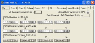
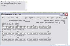
I was online with the PLC, cleared the fault, changed the status bits (the first line only) and put it back into run. It still didn't work.

I cleared the fault again, changed both lines of 1's to 0's, and it still gave me the fault.

Slots 0-3 are my processor, an ethernet card, and two basic modules. 4-30 are my IO.

I've attached a couple of screenshots.

error.JPG
 
I think the actual detected rack size has to match.

Unfortunately, you're going to have to remove or re-address quite a bit of your logic because the SLC program won't compile if you reference I/O that is in slots that don't exist.

I'd say just go ahead and do the heavy lifting of replacing the I/O addresses with fake N-file addresses, and set the actual rack type to fit the one that's in your office. That should allow you to compile, download, and go to run mode to test your HMI application.
 
with the slc 500, you are only allowed to connect up to a total
of 30 cards (1 cpu and 29 i.o cards) without using remote i/o, devicenet, or some other method.

you stated (2) 13 slot racks and (1) 7 slot rack.
that's a total of 33 slots. your processor may fault out on you for that reason.

regards,
james

Logix500 won't allow one to build that configuration. It restricts the I/O list to 30, regardless of 33 slots.

D'oh, I see Ken was typing as I was Editing :) (I had to open up Logix to prove the 30 slot thing as I honestly have never had that many local racks....Remote I/O baby!)
 
Last edited:
Good eye, James, but the way it works is that only 30 slots are addressable.

If you, for example, connected three 13-slot chassis together, the CPU slot and the first 30 slots would be addressable, leaving 8 slots empty and unusable by the SLC controller.

I don't have an SLC to test with for certain, but my recollection of doing just such a system was that I had only the first rack on the bench and could not go to RUN mode until I deleted or changed the I/O references to the second rack.
 
If you can get RSLogix 500 Emulate, then it may allow you to do much of your logic testing, although it will not emulate PID loops and there are limits to what it can do with communication.

If you need to use the real processor for testing, here is what I would do:

1. create a ladder file called "Inputs" and make a JSR to it at the beginning of the main program.

2. create a ladder file called "outputs" and make it the last JSR in the main program.

In those two ladder files, you will map the real I/O to internal bits which are used in the main logic of the PLC. Any I/O that can't be addressed in the test setup can be listed like this:

B10/0 B10/0
---] [---( )---

This way, they are still there in the input map (or output map) to remind you that they need a real world assignment in the finished project, and you can right click and "toggle bit" to test the main program.

Also, you can add a ladder file for testing purposes that can simulate the I/O, for example if a motor starter output bit is turned on, then 3 seconds later a limit switch input should come on. This can be a lot of extra work for a complex machine, but can save lots of debugging during start up which could result in great savings. When you put the code in the real machine, you can remove the test code (or remove the JSR to it), and "fill in the blanks" of the I/O map to match the real machine.

By using the I/O mapping method, your machine control logic can be tested without real I/O, and you can plug in the real addresses later when you have the full rack setup.

It is also a useful method for dealing with last minute changes or errors that might occur during installation. You can invert the state of discrete devices quite easily in one place, and block or jumper devices that have failed or are not yet functional.

Paul
 
Thank you for the suggestions. Like Ken said, only the first 30 slots can be used - the last 2 slots on the 7 slot rack are unused.

Remote I/O would have been awesome. Since we aren't doing the actual PLC work (the PLC code is existing - we are doing the HMI and electrical), we didn't have any control over which PLC was installed. The majority (20 of our IO cards) of our I/O is from a switchgear located in the same room as the PLC Panel, so RIO wasn't considered.

Also, unfortunately, looking through the code, there is no input mapping routine or section of the code that could be easily removed for testing. The original programmer used the actual input contacts throughout the programs, instead of mapping them to N or B addresses. Since the PLC code is considered existing and it operates properly in the currently installed system, I don't think we have much of a chance of convincing him to remap the IO to N registers.

RSLogix Emulate - The last time I tried to use this program, I couldn't get it to work. Has Rockwell upgraded it to be more user friendly? With emulate, can you assign it an IP address and connect to it as you would a regular processor, using an IO server (we use Kepware).

Thanks,
Steve
 
Paul -

Thank you for the reply - I think I was typing my last response while you posted :)

I have had the same suggestion with mapping inputs from a couple of the AB guys in the office. Unfortunately, I don't that will be possible (see above).

I am going to give RSLogix Emulate a shot - hopefully we can get that working and get it to talk to Kepware.
 
sthays10 said:
RSLogix Emulate - The last time I tried to use this program, I couldn't get it to work. Has Rockwell upgraded it to be more user friendly? With emulate, can you assign it an IP address and connect to it as you would a regular processor, using an IO server (we use Kepware).

Thanks,
Steve
I believe the latest version does have quite a few enhancements:
EDIT: link fixed: http://www.rockwellautomation.com/rockwellsoftware/design/rslogixemulate/sysreq.html

I believe you can connect to any remote OPC data server using RSLinx (not Lite). I have successfully connected it to Factory Talk View using RSLinx Gateway as the OPC server. RSLinx Lite will not allow you to use the OPC functionality.

RSLinx sees the Emulated PLC as a real processor, so anything that connects through RSLinx should still work.

I have no experience with Kepware drivers.

Paul
 
Last edited:
Kepware may not connect directly....All depends on whether the Kepware OPC server supports emulated processors as a client. I know that in Wonderware for example, using the DAServer, it will not. So, as Okie suggested, as a temporary get around, just use RSLinx (not lite) as your OPC server as Linx does connect to an emulated processor.
 
We haven't found a way to get Kepware to talk to the emulator, yet. I haven't had the need to set up RSLinx as an OPC client before. We have RsLinx Classic 2.54.

When I set up the RSLogix 500 Emulator, I had to set up the RSLinx Driver as SLC-500 (DH485) Emulator. I could then download to the Emulator.

How would I set up an Ethernet driver in RSLinx to look at the Emulator using DH485? This is where the OPC/DDE client comes in, and I'm not sure how to set it up.
 
You cannot configure an Ethernet driver to talk to the emulator. Your "emulate" driver (DH485) must be used. When you have the driver setup you can go into RSWho and browse the emulated processor. Right click and "configure dde/opc" and that will allow you to set a topic name which points to the emulated PLC using the emulate driver in linx. RSLinx is the OPC server, from which you should be able to connect to the RSLinx OPC server with any OPC capable software. You just need to configure it so it points to RSLinx as the server, and it should pick up the topic names.
 

Similar Topics

Hello. I am trying to change the indexes when I Paste from SLC Library and I must be doing something wrong. I tried it with a very simple rung to...
Replies
5
Views
1,416
Hi all, yesterday I was at a customer site doing a PM and after making a couple of minor mods to the program, I went to back it up to EEPROM (yes...
Replies
2
Views
2,387
I have a few projects I want to Save As file type SLC to be able to use the Translation tool in Studio 5000 (migrating from SLC 5/03 to...
Replies
3
Views
2,491
Hi all, Sorry to make my first post a request, but I was given this .RSS file and need to convert it to .SLC - would some helpful person with...
Replies
7
Views
4,510
Hello. I am learning Allen-Bradley PLC programming using the RSLogix 500 emulator. So I need some help pls. I am using the RSLogix Microstarter...
Replies
8
Views
4,259
Back
Top Bottom