Question about using limit switches or optical sensors

kevilay

Member
Join Date
Feb 2009
Location
Ontario
Posts
174
I am setting up a basic plc operation and am going to have it detect the length of a dowel (ie 1/2in pin) they will be between 2 inches and 4 inches in 1/2 in incraments. I was just gonna have them line up against a base and set a limit switch or optical sensor every half inch so it knows what size it is and how to sort it. What would be the most cost effective way to do this? Im am an electriconics student. I wasnt sure if some of the cheaper optical sensors would be accurate enough to measure within that half inch difference? Any help would be greatly appriceated.

Kevin
 
There are plenty of sensors that would be sensitive enough for the job, but it's difficult to help you pick out the right one without more information about the project. If the dowels are metallic, you might do the job with an array of inductive proximity switches. You can get them in small diameters so that they can be spaced very close together. I should warn you though that some sensors can interfere with each other when mounted that close together.

If you choose optical sensors, you may want to look at a barrel type or some with fiber optic cables so that they can be fitted that close together.

You may also want to look at something like this:
http://www.bannerengineering.com/en...ing-Array-Sensors/424/A-GAGE-EZ-ARRAY-Series/

The Banner Engineering website is a great place to research this, and their products are both economical and highly regarded.
 
price is my most concern :p Im just a student so efficiency or anything like that isnt much of a concern its moroso to display what i have learned. I could separate the sensors by a fair bit and just make it so their is more then 1 reading station. Im just looking for something that is cheap and will trigger pretty fast and accurately.

Kevin
 
price is my most concern :p Im just a student so efficiency or anything like that isnt much of a concern its moroso to display what i have learned. I could separate the sensors by a fair bit and just make it so their is more then 1 reading station. Im just looking for something that is cheap and will trigger pretty fast and accurately.
Kevin

OK now we are getting places
1. This is a student project.
2. You do the work make mistakes (sorry that is part of learning)
3. We will help

You want to sort 4 different size objects whose size varies by 1/2" increments.

Befor you start worrying about what you are using as a sensor
1. how are you going to handle them to enable the sensor to detect.
2. How are tehy moved
end to end on a conveyer
or slide or side by side on a conveyer?
3. After you are able to discriminate length - what are you going to do with them and how? How are you going to get the 3" in the 3" box and so forth for other sizes?

Dan Bentler
 
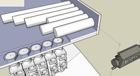
Im not 100% sure how Im feeding them, but i work in tool and die so i have full access to all sorts of machinery and steel. What I have in mind is running them side by side and letting them roll by gravity and use a feeder with a vibrator to drop them out. So one end of the dowels will be against a wall and the other end will be sticking out somewhere between 2in to 4 in based on the size of the dowel. I was thinking maybe I could check if its 2 inch, then move it long otherwise and then check 2 and 1/2 or vise versa. If it detected true I was goin to use a solenoid or something like that to pop it out of the row, down a shoot into a box. sorry for not being so precise at first, hope this can help.

Kevin
 
Great drawing Vaughn

If you can get photoeyes on 1/2 inch centers then I suggest aligning the array 1/4 inch back toward the flush end.

If the rolling surface is tilted slightly toward the flush end it will help in the alignment.
 
Yes, great drawing, you are fast too!

Kevin,

If you can separate the dowels by some distance, even an inch or two, that will make it much easier to get accurate detection by the sensors. With them close together, you could trigger two adjacent switches at the same time.

For this student project, you could use some type of belt with spacers. To keep it cheap, the belt could be a piece of fabric wrapped around a couple of end pipe rollers, with small wooden sticks glued onto the fabric to hold each dowel at a certain spacing from the other dowels. Like Bernie says, tilt the rolling surface slightly to keep the dowels aligned against a base.

Hey, you said 1/2" diameter dowels. Could they be 1" or even 2" diameter? That would help make sure that your sensors only detect one dowel at a time. It is the space between the adjacent dowels that you have to worry about, when two dowels are over the sensor position, equi-distant from the sensors. By making the dowel diameter larger, the sensors will be less likely to make false readings.
 
Last edited:
I was thinking maybe I could check: if its 2 inch, then move it along; otherwise check 2-1/2, or vise versa. If it detected true, I was going to use a solenoid (or something like that) to pop it out of the row, and down a shoot into a box.
Kevin, if your sensors are not lined up in parallel across the "chute" as Vaughn showed, but instead are in series, so that only one length sensor is triggered at each position, then you would probably want to put the large 4" length detector first upstream, followed by the 3.5", then then the 3", and so on. This would allow you to kick off the longer pieces first. If you do it the other way, with the 2" sensor first upstream, then the 2" sensor will see all pieces and kick them all off at the 2"-kick position, even if the dowels are actually 4" long.
 
Another question to consider: Will the sensors work better if they are underneath the rolling surface, or overhead?

The answer to that question depends on what type of rolling surface and what type of sensor you are going to use.

If the rolling surface is metal, then I think it would more difficult to keep a proximity sensor from detecting the metal surface instead of the dowels. If the sensors are underneath the rolling surface, they will need to be looking up through holes, not protruding. The cutout holes could cause the dowels to stop rolling and hang up, if they are rolling by gravity only. You would certainly want to use small-diameter sensors and larger-diameter dowels to help prevent the sensor holes from catching a dowel, or causing one to turn sideways.

If the sensors are photoswitches or optical detectors, a metal surface is less problematic, but the sensors will need to be within a certain distance range from the dowels. A wooden surface would work for all types of sensor.

If the sensors are suspended overhead, then using a metal rolling surface is also less likely to cause false trips. Also with overhead sensors, you could use a belt with spacers, so that kicking a particular dowel off the belt is less of a problem than if they are all close together and moving. Many package handling and routing systems use rubber conveyor belts and overhead photoswitches to detect the packages and kick them off onto another conveyor. The packages are always put on the belt at some minimum distance apart.

Whichever position the sensors are in, you probably will need to hang them with adjustable mounts so that the sensing distance can be changed to get the best detection.
 
Last edited:
wow you guys are great, Im gonna kick some of these ideas around, I think it will be easiest to put the sensors in serious and a belt with spaces sounds like a really good idea.

Thanks alot for your help
kevin
 
The belt only needs to be about 18" long, with spacing blocks (separated by the diameter of the dowels) attached to create cleats or "slots" on the belt. The spacers should be semi-circular, so that a dowel falling onto the belt will roll into the nearest slot. You could make those by splitting some 1/2" wooden dowel rods in half with a band saw. Then hot-glue or sew them to the belt, so that only one dowel can fit into each slot on the belt. If your metal dowels are 1/2" diameter, then your slots can be about 1/2" wide. You might even find an abandoned piece of cleated belting that would work.

You could design a feed hopper with a slot that only allows one dowel to feed out into each slot on the belt. You could move the belt with a simple crank rod attached to the roller on one end. As you turn the crank by hand, the dowels should roll into a belt slot, get moved past the sensors, with the longest sensor first, down to the shortest sensor. At each sensor position, you will have a solenoid that (if that sensor is triggered) will pop out and kick the dowel down a chute on the opposite side. Make the chute wide enough to allow for small variations in the time when the kicker pops out. Because the dowel will be moving, each one will be sensed and popped off at a slightly different place. In other words allow for the tolerances of your system. Your discharge chutes probably will need to be at least 3 times wider than your dowel diameters. Your kicker solenoids need to be slightly downstream of the sensors. It takes some small time for the kicker to get moving and contact the dowel. Because the dowel is moving, you are shooting at a moving target and you must aim slightly past the point of detection in order to hit the target dead center, just like shooting at a running man. The amount of "lead" depends on the speed of the belt. You can demostrate to your instructor that as you turn the belt faster, at some point the kicker will miss the dowel or will only hit the trailing edge.

What happens if there is still a dowel left on the belt after the last sensor? Most material-handling systems have a last-ditch position, the Reject bin, for those items that did not get routed for whatever reason - too big, too small, out of position, or simply a sensor misread. You could have a last kicker for those, which are usuallly checked and handled by hand.
 
Last edited:
wow you guys are so helpful, any ideas what I should use to kick out the dowels? Kevin

Yes I do.

Reread what Lancie wrote. He almost gave you the answer.
Go do a little homework and come back with your ideas. You are a student go do some learning.

Are you just out of high school and have never been in industry? If that is the case then you get a little more tolerance and help.

Dan Bentler
 

Similar Topics

Hi all, I'm working on a safety circuit and had some question about fusing. Incoming supply - 120V/15A Power supply - PSL-24-060...
Replies
5
Views
582
I know this can be done, but I can't get the router config right. My goal is to physically connect(using an ethernet cable) a device(PLC, RTU...
Replies
9
Views
1,019
I'm a novice with Rockwell s/w and a rookie working with virtual machines. I needed a way to support multiple FTView ME versions. so I set up a...
Replies
5
Views
2,961
I am looking to fuse only the commons of my IO cards to protect the plc. Each input point is rated at 6.5 mA with a total of four points, in...
Replies
2
Views
2,755
I operate a distillation column for Argon gas. It has a pressure controlling valve that cools a condenser at the top of the column with nitrogen...
Replies
4
Views
2,272
Back
Top Bottom