PLC 5 BTR BTR Analog Module install question

bbear

Member
Join Date
Dec 2006
Location
ohio
Posts
63
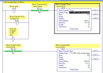
I am trying to add a 1771-IFE A Analog Input Module 12 Bit to an existing PLC 5/40 8 slot Chassis to read a transmitter signal on Input 1. I believe I configured the Module correctly using the berg jumpers and AB Publication 1771-5.45. The Program is using ½ Slot addressing and has the Processor in slot 0, 120vac input card in Slot 1, 120vac output card in Slot 2, 120vac input card in Slot 3, PS Slot 4, 120vac output card in Slot 5. That is the existing I am trying to install the Analog Input Card in Slot 7. Reading the Literature I have the Block Transfer operating without errors (see attachment) however I connect my Loop Calibrator Current Source to the first 2 terminals and cannot see, looking at N17 Data Table, the signal changing. Thanks for all the help form this site. I am trying to follow the
site structure and working through the problem but I am stuck on this. I am learning the AB products as I go.
 
N17:0 length of 12 would be N17:0-11
The next bt you have N17:1 which is already in use
I am just guessing that is your problem never have installed one of these in Plc5
 
N17:1 is not used in the program.
Yes it is...

By specifying a block transfer with a length of 12, N7:0 through N7:11 are all definitely being used.

Try changing the Data File address of the BTW to N7:12

EDIT: I think your BTW length is incorrect. Shouldn't it be 37 words?

Paul
 
Last edited:
I agree with iggy, your read data is overwriting your write (configuration) data. The first unused address you have in N7 is N1712.
Have you configured the write data?
There is also no need to alternate the write with the read - once the write is performed once (test the powerup bit in the read), you really don't have to do it again.
 
This is my opinion of what I saw in your attachment

I am trying to add a 1771-IFE A Analog Input Module 12 Bit to an existing PLC 5/40 8 slot Chassis to read a transmitter signal on Input 1. I believe I configured the Module correctly using the berg jumpers and AB Publication 1771-5.45. The Program is using ½ Slot addressing I see this as probably 2 slot addressing as you have set up rack 0 group 3 and has the Processor in slot 0 The processor is in its own processor or adapter position on your left hand side thus moving your slots the cards are in down one number , 120vac input card in Slot 1, 120vac output card in Slot 2, 120vac input card in Slot 3, PS Slot 4, 120vac output card in Slot 5. That is the existing I am trying to install the Analog Input Card in Slot 7 this would have this card appearing in slot 6 which in 2 slot addressing would be rack 0 group 3 module 0 . Reading the Literature I have the Block Transfer operating without errors (see attachment) however I connect my Loop Calibrator Current Source to the first 2 terminals and cannot see, looking at N17 Data Table, the signal changing. Thanks for all the help form this site. I am trying to follow the
site structure and working through the problem but I am stuck on this. I am learning the AB products as I go.
 
Last edited:
Paul I changed the BTW to N17:12, I searched for N17:12 and it was not found.
Mike I am not clear on Config. the Write Data?
I was alternating the write & read because of the example in the text.
I will fix that.
 
Paul N17:12 have same problem.
Gil the existing card beside the Processor is addressed I:000 the next Card is addressed O:000. That is the reason I said it is 1/2 Slot. Is this wrong and my BLKxFER Group 3 Mddule 0 wrong? I made a mistake in my typing at the beginning of my question; the Analog Module is in Slot 6 (next to the last slot), sorry.
 
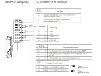
You seem to be unsure about the addressing, it is configured by dip switches. See picture below. You can also ses this under processor status.

Post your .RSP file. Zip it first.

dipswitch.jpg
 
See Picture below
If you add the card to your I/O configureation you can setup the card easier.
See revised RSP file. Double click on the BTW/BTR setup screen.

analogBTW_BTR.jpg
 

Attachments

  • Rev1.zip
    28.4 KB · Views: 20
Last edited:
I'm not sure about the rest of it, but your Read / Writes are still overlapping.

Change the Length in the BTR from 12 to 20

Change the Data file entry in the BTW from N17:1 to N17:20

Change the Length in the BTW from 12 to 37
 
Last edited:
Thanks guys very very much for the help. I hope one day I can assist people working on issues as you all have me. I have learned so much during this. I have the channel needed reading 2ma-10ma = 0-4096 counts. How can I set the range to 4ma-20ma = 0-4096 counts?
 
If you have added the module to the I/O documentation in RSLogix5 as suggested by Mickey, then you can double click that module to open up a user friendly method of viewing the module data and scaling. from that dialog, you can make changes to the scaling and have RSLogix send a one time configuration change.

If you have not added it to the I/O list, then go ahead and do that.

Here is a link to some useful information to get the existing BTR/BTW data into the configuration dialog box in RSLogix5:

http://www.plctalk.net/qanda/showthread.php?t=20002&highlight=PLC5

My post number 7 shows how to get the RSLogix5 in sync with the PLC5 BTR/BTW data without having to type it all in. Ron Beaufort has some great stuff in that thread also.

Paul
 

Similar Topics

Hello, I am trying to create a network status map at a plant. I'm assuming the comm status bit of dnet nodes is in the BTR/BTW instruction that...
Replies
0
Views
971
I set up an analog card (1771-IFE/A) in differential mode, this gave me 8 functional analog inputs. I used the RSLogix generated rungs with a BTW...
Replies
8
Views
3,746
Hello all, I am adding a 1771 VHSC card to an existing system in order to more precisely control part positioning. The problem I am having right...
Replies
2
Views
2,794
I have an application that is duplicated on a similar production line. A 1794-IE8 Flex I/O module is installed and connected to 4 pressure...
Replies
2
Views
2,435
Hello, I'm new here and looking for some help from you all. I'm writing BTR and BTW instructions in RSLogix 500 for a 1794-IE8 card with...
Replies
1
Views
7,263
Back
Top Bottom