1771-IFE --- Need HELP understanding BTR and BTW!

Lakee911

Member
Join Date
May 2006
Location
Columbus, OH
Posts
98
So, I have a 1771-IFE set up for 16 single-ended analog inputs. Currently only 7 of them are being used. We need to add 5 more inputs.

This is my current config

BTR Block Transfer Read:
Code:
Rack               000
Group                5
Module               0              
Control Block     N7:0  
Data File        N7:10
Length              11
Continuous          No

BTR Block Transfer Write
Code:
Rack               000
Group                5
Module               0              
Control Block    N7:21  
Data File        N7:30
Length              19
Continuous          No


I read through the user manual for the 1771-IFE, and the BTR/BTW instruction help file, but I am still confused. First of all, what is the difference between the Control Block and the Data File?

About the only thing that I have figured out is that the current input data currently resides at N7:14, :15, :16, :17, :18, :19, :20. After properly setup, the new data will be at :21, :22, :23, :24 and :25. I think there will be some overlap though.

So, according to the manual I'll need to change the lengths from 11 and 19 to 16 and 29, respectively. I think there will be some overlap though.

Can someone help?

Thanks!
Happy Holidays!
 
The control block stores all the data in the instruction (rack, grp, etc. The data block contains the data going to (BTW) and from the module (BTR).
No overlap is allowed! For either the data files or the control blocks.

Since you have to change the location of one of the data files, why not go to the max length for each (20 for read, 37 for write)?
 
So, the Control Block is reserved in processor for the BTR/BTW instruction itself. Great! Makes sense.

I think I've got this figured out. That was the key. :D

Thanks, All!

Jason
 
and make sure that you check the appropriate series when you consult the books ... the newer one (series C) uses a slightly different layout than the older A and B types ...

also ... make SURE that the internal jumpers located INSIDE the module are set correctly for your new signals ... (voltage, current, single-ended, etc.) ...
 
Minor snafu ... maybe ... current BTW data shows N7:48 (Gain calibration, I think) to read 3000 in hex. That's bits 12 and 13 (for channels 12 and 13) set to 1. Those need not be set and is probably a mistake, no?

Thx
 
no - a PLC-5 system is NOT designed for "Removal and Insertion Under Power" - as the ControlLogix buzzword goes ...

now I have heard of people doing that in emergency situations - and SOMETIMES getting by with it ...

BUT ...

if keeping the process going is so "critical" then you're certainly making a VERY STRONG argument for shutting down the process in an orderly fashion BEFORE you remove/insert a module ...

I know for a fact that SOMETIMES a PLC-5 system will come to a screaching halt if you remove/insert a module while the system is running ... (usually the processor doesn't "fault" - but the I/O signals get "stuck" and hung up - and not necessarily on the same module that you're working with) ...

personally, I wouldn't do it ...
 
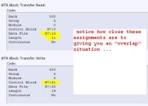
oops! ... be careful here ...

take a look at the figure below ...

you need to CAREFULLY "map" these assignments out ... you can't just simply increase the "length" numbers the way things are currently set up ...

personally I'd get a piece of paper and chart the addresses and what they're being used for (something like a spreadsheet) ... there's a VERY real chance that you're going to have to reassign the locations of some (or ALL) of your existing signals to make this work ...

note to former students: THIS is a prime example of why we "leave some slack" when we set these things up during the analog exercises ...

overlap.JPG
 
That's exactly what I'm doing at the moment, Ron. I'm believe that I will be able to move the current BTW stuff to another file and use that space for the BTR.

I do have data (as in it is not zero) at N7:22, :23, :24 and :25. When I cross reference this I don't come up with those addresses being used anywhere in the program. Is it safe to assume that this is extraneous
data and that it's doing nothing?

Thx!
 
I do have data (as in it is not zero) at N7:22, :23, :24 and :25. When I cross reference this I don't come up with those addresses being used anywhere in the program. Is it safe to assume that this is extraneous data and that it's doing nothing?

NO! – please be careful here ...

according to the present "Control Word" assignment of your existing BTR, those words ARE being used ... they're part of the five-word long control block ...

quick question: did you (or did you NOT) read that post about the mailman that bbear linked in post #2 above? ...

if you haven't read it – I HIGHLY recommend that you stop and read it now before you go any further ... that thread is over six years old - but it STILL gets a lot of hits ...

and MAKE SURE that you have a good backup copy of the program the way it was working before you make any changes ...
 
Last edited:
I did read it! Honest! I guess I just missed that 5 word long part about the control block (opps). I'll go read it again now.

But, like I said, I'm moving the BTW to another file. :)

Edit: Actually, it's kind of implied (maybe) now that I know it, but it doesn't explicitly state it.
 
Last edited:
OK ... I've seen a lot of people get into trouble with this type of operation ... it can be a royal mess to straighten out ...

going further:

you might not have the luxury of doing it this way, but the RSLogix5 software can actually write the BTR/BTW rungs for you automatically ... since you might have to relocate things anyway, you might want to experiment with the "Insert Ladder Rungs" button on the module's setup screen (in the IO Configuration feature) ...

I'll be offline for the rest of the day in a few minutes - but there are plenty of forum members who can help you if you need it ... (although it's really pretty slow here today because of the holidays) ...

I hope this has been helpful ... good luck with your project ...
 
It has been very helpful. It is a bit slow but that's okay. I'm glad you were here today. I'm going to be leaving here soon myself to enjoy the holiday. :)

I'll be in the field next week one day to download the latest program so I can be sure that my changes aren't in vain. I've still got a bit of time before I need to implement the changes.

I don't trust those auto things ... I would rather do it myself so I know and understand what it did.

Thanks!
 
Whoever set this card up originally didn't do you any favors by "saving" a few words in the N7 file. I always set up the BTR and BTW for the full configuration. I also like to use one file for BTRs and one file for BTWs. For example BTR Control Block N11:0, Data File N11:5 with BTW Control Block N12:0, Data File N12:5. The next card would be Control Block N11:50, Data File N11:55 with BTW Control Block N12:50, Data File N12:55. Yes, it "wastes" some memory, but it's very easy to understand. Unless you have an old PLC5, you can use BT file type for the Control Blocks and keep that out of your Data File which makes it even cleaner.

I also recommend using the wizard to configure your card. The configuration of the card is contained in the BTW data file. If you change the location of the data file for the BTW, the configuration will be "lost" unless you re-enter it. The wizard presents the data in a much more readable fashion than the data table. Search here for more info, I know there are some good threads about it.

On the "checked the cross reference" subject... If you go to the data table and press the "Usage" button, it should show that memory in use. In the PLC5 world, this is an important step in checking if an address is used.
 

Similar Topics

to get straight to the point im working with a PLC-5/20 programmable controller, is mounted on a 1771 a3b1 12 slot chassis. it has 1771 ofe and...
Replies
8
Views
8,301
Hi: I recently tried connecting 2 new single-ended 4-20mA analog inputs to an existing 1771-IFE. The IFE is in a RIO chassis. The values coming...
Replies
4
Views
1,399
I'm having issues saving the individual channel settings on a 1771-IFE Analog card. We recently swapped from 0-10v to 4-20ma transducers. I...
Replies
4
Views
1,009
We will repair by ourselves at first by replacing few power ICs such as 78M15,79M15, 79M05 and T3055E. What is TE055E Motorola TO-252, Transistor...
Replies
1
Views
1,693
Hello. Wanted to ask you seasoned vets out there about a scaling issue I'm having. Controller migration. A 1771 IFE 0-5VDC analog signal...
Replies
3
Views
2,510
Back
Top Bottom