beginner:changing powerflex 40 speed

PcRider

Member
Join Date
Dec 2009
Location
Weir KS.
Posts
32
We are working on a project in class, so far we have only the basic commands, user, timers, as well as some math-compare instructions.

We're using the micrologix 1000 plc.

We have already wired up a powerflex 40 using relays to start a motor going forward on O:0/0, then backwards on O:0/1. Also we have the speed preset controls set up on O:0/3, O:0/4, and O:0/5.

So far so good.

Now we're suposed to run the motor one dirrection, change speed several times, reverse the motor, and change speeds several times again, and start over. Things like stop, start, acceleration, and deceleration are not required.

I've been looking at some of the traffic light programs, and thinking I could just modify the "lights" to be motor speeds, and write the needed outputs for each speed in paralell on seperate lines.

Nothing I have come up with seems very proper to me. I might be able to make it work, but I think I could do better than that.

Any suggestions on how to plan this thing out, and start putting something like this together?
 
One way is to use a timer to start the motor, and then when that timer times out, have the output of the first timer start a second timer. Cascade timers and use the .dn bits to enable your outputs.

If you want to get fancy, you could do it with just one timer that increments a counter. Bit-shift as necessary, or re-wire your drive. ;)

Look over the timer, counter, & (maybe) bit-shift instructions in the Micrologix programming guide to see exactly how to do it.
 
I deduce from your post that you need to vary the speeds from the PLC, not just select preset speeds since you already have that on 3,4, and 5.

You have two choices: first use a digital to analog card to provide a variable 0-10VDC analog signal that the drive receives as its speed reference. Or, you can use two of the relay inputs to the drive to do an increase/decrease speed control. Look in the drive Instruction Manual for something called Floating Point or MOP control. This eliminates the need for an analog card and uses two digital outputs instead.
 
One way is to use a timer to start the motor, and then when that timer times out, have the output of the first timer start a second timer. Cascade timers and use the .dn bits to enable your outputs.

If you want to get fancy, you could do it with just one timer that increments a counter. Bit-shift as necessary, or re-wire your drive. ;)

Look over the timer, counter, & (maybe) bit-shift instructions in the Micrologix programming guide to see exactly how to do it.

I was leaning towards cascading timers, I'll try that first. Thats kind of how the trafic light thing works. I'm not familiar with bit shift instructions at all, and rewiring is not allowed. I'll look into bit shift later after I get this thing working.


Thanks for the reply :) PcRider
 
I deduce from your post that you need to vary the speeds from the PLC, not just select preset speeds since you already have that on 3,4, and 5.

You have two choices: first use a digital to analog card to provide a variable 0-10VDC analog signal that the drive receives as its speed reference. Or, you can use two of the relay inputs to the drive to do an increase/decrease speed control. Look in the drive Instruction Manual for something called Floating Point or MOP control. This eliminates the need for an analog card and uses two digital outputs instead.

Actually we wired the digital inputs so we could use the presets. This is a programming question using this setup, I'm sorry, I guess I should have made that clear.

PcRider
 
I was leaning towards cascading timers, I'll try that first. Thats kind of how the trafic light thing works. I'm not familiar with bit shift instructions at all, and rewiring is not allowed. I'll look into bit shift later after I get this thing working.

Hmmm, it seems that my dog ate my first response, oddly appropriate considering... :)

Check out page 69 of the drive manual (22b-um001_-en-e.pdf).

You will find that you can select eight different speeds using a combination of your three digital inputs to your drive (your O:0/3, O:0/4, and O:0/5 outputs).

You could then step through these speeds by "counting up". But since your speed bits start three bits off from bit zero (O:0/0), you would have to shift them over to fit into your outputs.

You could then decrease your speed by counting down.

This should be enough of a hint.


Thanks for the reply :) PcRider

Anytime. :)
 
Last edited:
You could also do it with one timer. Then use compares to turn on your preset speeds.

.acc is less than X, turn on speed 1
.acc is between X and Y turn on speed 2
.acc is greater than Y, turn on speed 3.
 
Hmmm, it seems that my dog ate my first response, oddly appropriate considering... :)

Check out page 69 of the drive manual (22b-um001_-en-e.pdf).

You will find that you can select eight different speeds using a combination of your three digital inputs to your drive (your O:0/3, O:0/4, and O:0/5 outputs).

You could then step through these speeds by "counting up". But since your speed bits start three bits off from bit zero (O:0/0), you would have to shift them over to fit into your outputs.

You could then decrease your speed by counting down.

This should be enough of a hint.


Anytime. :)

I ended up using the cascading timers to trigger each speed change by latching/unlatching the needed outputs in parallel with the timer operation. Poor wording sorry. The tricky part was using the outputs again and again. I solved that problem by using the b3 file as a buffer. I would change the b3 file inputs, but never change the b3 file outputs.

I am still curious about using the shift register. I was not able to piece together how this could have helped. I do understand I can shift the value right or left, "but", for that to help would seem to suggest that I can write all three outputs for speed control in one command?? Otherwise what is the point in usng shift registers in the first place?

Reading and writing bytes, or words to inputs/outputs would certainly be a nifty trick to know!! How could I tell it (micrologix 1000) to to write 000110 (for example) to the outputs in one command?

For that matter reading bits from several inputs into bytes that I could then use as data for nearly unlimited manipulation would also be a neat trick.

~Heavy Sigh~

This is all to much to ask for a simple explanation I'm sure. Maybe you could explain a little about the shift registers though?

Thanks PcRider
 
Reading and writing bytes, or words to inputs/outputs would certainly be a nifty trick to know!! How could I tell it (micrologix 1000) to to write 000110 (for example) to the outputs in one command?

For that matter reading bits from several inputs into bytes that I could then use as data for nearly unlimited manipulation would also be a neat trick.

Try:

MOV
Source 6
Destination O:0.0

MOVe sends a 16 bit "word" to a word destination address. the constant 6 (binary 0000000000000110) could be replaced with an internal address like N7:0 or B3:99. Then you don't need a bunch of MOVes pointing to the output word, only one at the end of the logic. Your ladder code could then MOV different sources to the internal word location depending on which state the machine was in.

Note that you can address the B file or the N file or even the I (input) and O (output) files at the word level and/or the bit level. Bit level addressing uses the "/" delimiter to tell the controller that the next values will be bit values.

The thing is, you may not want to overwrite the whole output word just to control 3 or four bits. You might have other stuff hooked up to those other points.

So that's where MVM comes in (masked move). It lets you move your source through a mask to the destination. The mask lets you decide which bits get passed through and which bits get left alone:

MVM Examples (assuming destination bits were all clear beforehand):
000000000110 Source
000000000111 Mask
000000000110 Destination

111111111110 Source
000000000111 Mask
000000000110 Destination

This should get your wheels turnin'

Absolutely gets my wheels turning, Thanks OkiePC, exactly what I needed to know!

I'm looking forward to doing some practice with these commands now. I'll have to make sure I can make them work right, then make sure I don't forget them.

Thanks again, PcRider
 
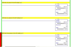
Another method of shifting bits in a word is to multiply the word by powers of 2. See examples below. Note the position of the bits after the word is multiplied by 2,4 and 8.

BitShifting.jpg
 
How's it coming? The other guys showed you how the bit-shifting and masking works, have you figured out how to put it all together?

The way that I would approach the project would be to:

1) Create a timer to setup a timebase for speed/direction changes. Say, 5 seconds.
2) Each time my timer timed-out, I would add 8 to a register (why 8?), and then reset the timer to allow it to start timing again.
3) Map the register count into your outputs, OkiePC and Mickey showed you how to do this.
4) Turn on your direction bit. No need to map this one.
5) When your count reaches 56, run the drive at that speed for the duration of that cycle, and then start subtracting by 8 to slow the drive down.
6) Lather, Rinse, Repeat.
 
How's it coming? The other guys showed you how the bit-shifting and masking works, have you figured out how to put it all together?

How its going depends on how you look at it. I have been learning to use the masked move instruction in my own original program. I'm learning alot!

The drawback is that my program did not even begin to implement using word addressing. I am also learning something about timing issues, and why you shouldn't use latches in a program like this. :(

At this point I will have to start over, there is just no way to make my original clusterbunch work predictably.


The way that I would approach the project would be to:

1) Create a timer to setup a timebase for speed/direction changes. Say, 5 seconds.
2) Each time my timer timed-out, I would add 8 to a register (why 8?), and then reset the timer to allow it to start timing again.
3) Map the register count into your outputs, OkiePC and Mickey showed you how to do this.
4) Turn on your direction bit. No need to map this one.
5) When your count reaches 56, run the drive at that speed for the duration of that cycle, and then start subtracting by 8 to slow the drive down.
6) Lather, Rinse, Repeat.

It will probably be something like what you outlined here when its done.
I'll keep you updated, Thanks Pcrider
 
It's a painful lesson, but a good one, lol. This thread has also helped me out a bit, since I didn't really know how the bit shifting and word addressing worked, nor did I know about the masked move.
 

Similar Topics

Hi all, Writng a FB in ST on Beckhoff TC for a pulser which turns on and off on a cycle, is paused by turning bControlInput to FALSE, but resumes...
Replies
6
Views
248
So to start off: I have no experience with PLC's, but I'm good at figuring stuff out, but I need some help to know if my PLC is just dead in the...
Replies
2
Views
114
Dear all, First of all thanks for letting me join this forum. I just need some help in one of my programming exercises. Being a beginner...
Replies
6
Views
608
I am trying to connect to SLC5/03 using an FTDI usb to rs232 with female to female converter at 1 end... however I can not connect to it ... the...
Replies
8
Views
1,269
First time poster here so long story short i built my own trainer at work so i could toy around with various things and test things and learn...
Replies
25
Views
2,146
Back
Top Bottom