I cant figure this out clx Input dropping out

kf5pv

Member
Join Date
Aug 2008
Location
Fort Worth
Posts
39
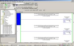
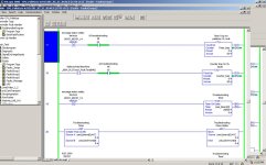
I have CLX 5561 that has some inputs that are dropping out and I cant figure out why. I have a counter to catch them dropping out and also a timer to see what the duration of the lost input is. I am seeing the counts on the counters but am not seeing any time on the timer traps. I put a branch around the input on the timer just to test it and my traps seems to work fine when I toggle the bit on and off. This is happening on at least two Inputs on this slot that I know of. I have attached an example. I would love to hear any input. (pardon the pun)
Paul
why.jpg
 
Well, I agree that when the tag I4[0].8 is false that the timer should increment and the largest value that the accumulated time gets to should be stored.

Cross-reference to be certain you are not resetting that timer elsewhere, is my only guess based on that I can see in the screenshot.

I4[0].8 is not a normal I/O module tag, so where is the input data really coming from ?

Have you used an oscilloscope or other meter to determine that the input signal really is not transitioning from true to false ?
 
Following up on what Ken mentioned about the input tagging have you mapped in the actual input from the module from a remote network, or is this module mapped in from the local rack? Is it possible the mapping is being halted or overwritten in some way?
The reason I ask is I had an instance of a remote ethernet rack with a flaky network connection showing a tripped overload block on a hydraulic pump motor (N/C Contact), cleared the problem by re-terminating the ethernet cable.
 
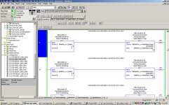
First off let me say Im not to good at this CLX stuff. OK. I see what you mean Ken about the addressing and I have attached a screenshot that might explain that. I have not checked with a meter or scope to see if I am actually loosing the input. I really dont think I am. There is nothing resetting the timer. I have the same thing in slot 10 happening on another input. I have a trap for that one too and it shows 0 time but I have counts on my counter for it. As far as ethernet connections there are no remote racks from looking at the I/O config. There is some flex I/O and Ill include a screenshot of something that makes me suspicious about it. This code is probably some really good German engineering but Im not qualified to say. I can say that the two inputs are sourced from the same 24vdc source. And yes both cards reside in the local rack, and there are no remote racks,(unless you include the flex I/O.) I wish I had 600 more times the knowledge about this than I do. Thanks again.
Paul

why1.jpg why2.jpg
 
Oh and By the way, This Is on Some motor over load blocks. About 15 of them that were daisey chained together. I have seperated them out to individual inputs to try to isolate the problem but this is where I am at now. There is also some code in rung 1 of this ladder that latches in a fault for this and stops the machine even though no overload triped. How can I have counts on the CTU's and no time in my traps that are right under the CTU;s???
 
Hi.
How can I have counts on the CTU's and no time in my traps that are right under the CTU;s???
You are using self resetting timers, as soon as the input goes back to false the timer.acc value gets set back to zero. If you want to save the accumulated time use a retentive timer (RTO).


BD
 
But shouldnt I trap the .acc value in the next line of code?
If I put a branch around the input on the timer and toggle the bit on and off that I put in that branch I capture that value in the next line and it holds the greatest value. I have also installed some counters off of the actual local input to see if those values change or if it something with my cps instruction.
I see now that I am also getting counts from the actual physical input but still nothing captured in the timer. If I were really loosing the input at the card I would think that I would be seeing some kind of count on my timer traps.
 
Last edited:
So, this is actually a DeviceNet problem.
What is your DeviceNet cabling like? Do you see any errors on the scanner module?
What speed is it running at?
 
So, this is actually a DeviceNet problem.
What is your DeviceNet cabling like? Do you see any errors on the scanner module?
What speed is it running at?
There no module errors on the DNET card. however under the backplane tab the transmit retry limit is 3. I waqs thinkinh it should be higher than that but not sure.
No; the input card is a 1765-IB32 in slot 4 and slot 10 of the local rack. I dont know what the reason is for the line of code identifying the slot of the device net scanner for the flex I/O and the VFD's on DNET.
I Realize I am confused but I think alot of the code is a template and much of it was never cleaned up. Could you have a input card in the same rack with the processor and it be flex I/O? if that is the case then Im sure it could be a DNET problem and I will need to go do some more homework.
Thanks,
Paul
 
Yuck... I've had that problem with a DNet setup, but never with a card in the rack. How is that fault program file scanned? Could it be that the condition is such (input off) that the counter counts immediately on the scan through that file and that the timer is enabled that scan BUT the next scan the input is back on and the timer is just reset without really accumulating any value?
 
Hmmm...
Seems to me if you only lose the input for one scan, then your counter will count, but your timer will always read zero.

On the scan with the input off, the counter gets a false to true transition and counts. The timer gets enabled but no time has elapsed yet. If on the next scan, the input is back on then the timer is zeroed before you get any value in the accumulator.

Edit: That's just spooky Russell (and yes, I type slow)
 
Last edited:
If you want to test that theory, put the accumulator move above the timer rung, then you will trap the accumulated value before the timer resets on the next scan.
 
If you want to test that theory, put the accumulator move above the timer rung, then you will trap the accumulated value before the timer resets on the next scan.

I dont think that will work as the accumulator should not be updated until the rung with the timer is evaluated. If the condition to the timer is false, then the timer will not be evaluated.
 

Similar Topics

I'm going to try to ask this question again, I think brought this up a few months ago maybe? Anyways, I have a (3) analog inputs going into a...
Replies
11
Views
3,573
this is my first time posting usally you guys already have a thread with my answer. I have a 1761 net ini ser D im trying to connect using a...
Replies
11
Views
4,548
Hi Guys, Haven't much experience with Logix500 and something I need to do which would be fairly straightforward in Logix5000 is rather difficult...
Replies
6
Views
3,263
This is simple to most i'm sure, but when I think i've got it, i find a flaw. I want p-9 to have priority over p-14. But if p-9 doesen't see...
Replies
2
Views
2,207
I have a sysmac omron plc C200H CPU01,only the power led is ON,using CX-ONE programmer software, and connecting to the plc via Host link LK202-V1...
Replies
2
Views
704
Back
Top Bottom