PLC 5 40E Addressing

Join Date
Mar 2008
Location
Nottingham
Posts
7
I have been given a project to do using PLC5. I have used the software before but always using I/O cards.
I am unsure as to how I address the PLC directly. I have attached a few screen grabs from what the customer has sent to me and of what the PLC is to see if anyone can help.
Sorry if this is a basic problem but I can't find any help on Allen Bradleys website so I thought I would try here.
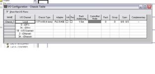
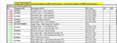
PLC.jpg Customer Requirement.jpg
 
One slot addressing... The inputs are I:0/0 through I:0/17 (Inputs and Outputs on the PLC5 are Octal, the IBD is a 16 channel input module.

The outputs are O:3/0 through O:3/17.

The 'Tag' should be assigned to the I/O point "SYMBOL", the 'Description' should be well, the I/O point "DESCRIPTION".

ETA - With Single Slot addressing on the 5's, just ignore the last part of the modules "R/G/S" designation, that stands for 'Slot' and will always be 0 with single slot addressing. The only parts you need concern yourself with are the "R" and "G" parts, which stand for "Rack" and "Group". You have a 4 slot chassis, it seems, as "Rack 0", so you then have the slots as I/O "Groups" 0 through 3. A 16 slot chassis would have two logical racks, each with 8 Groups, so in that case you would have I/O available from IO:00 to IO:07 for the first logical rack, and IO:10 to IO:17 for the second logical rack.
 
Last edited:
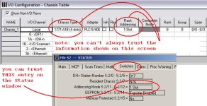
for future reference ...

well, if it works OK then don't argue with success ... just be aware that for future jobs you can NOT always trust the information that you see on the I/O Configuration screen ... all of that is "documentation" which starts out with default entries (which may or may NOT be correct) - and then is subject to human/programmer entries (which may or may NOT be correct) ...

tip: for the LOCAL chassis (the one with the processor in it) you really should check the "Switches" tab on the Processor Status window to determine the 2-Slot; 1-Slot; or 1/2-Slot addressing mode which is actually being used ... THAT information is developed by reading the actual settings of the DIP switches located on the chassis backplane ...

dont_trust_IO_Config.JPG
 

Similar Topics

Hello Everyone, I am reaching out to this knowledgeable community with a peculiar problem I've been experiencing with a PLC 5/40E. This issue has...
Replies
16
Views
2,276
Have a PLC5/40E that has a battery installed and a working battery warning light that is off with the battery plugged in. There is no memory...
Replies
8
Views
2,709
Please help me! I need to perform the firmware update for PLC 5 1785-L20E / 1785-L40E and 1785-L80E, but I do not find these firmware to download...
Replies
7
Views
2,391
I am trying to connect a PLC-5/40E to Ethernet via a 1761-NET-ENI. After reading several other forums and technical sheets I have connected the...
Replies
14
Views
5,127
Hi, We have a PLC 5/40E (1785-L40E/F) which is not working. We do have others like PLC 5/40, 5/60 and a 5/80 in our stock. I like to know if I...
Replies
1
Views
1,942
Back
Top Bottom