Sensors

mrtweaver

Member
Join Date
May 2007
Location
Bloomsburg
Posts
329
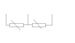
We have this piece of equipment that has on what appears to be two sensors. I have included a drawing of the schematic symbol used, although I am unfamiliar with the symbol. Thought maybe someone could tell me more about the symbol.

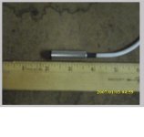
The details of the sensor are: Metal Housing, extended sensing tip, 1/2inch diameter metal housing, 1 1/2 inch long metal housing, 3/8inch diameter extended tip, 1/8inch long extended tip, extended tip is made of plastic, what appears to be where the actual sensing materials are is a 3/16 square discoloration in the center of the extended tip, it is a 3 wire sensing device, and it is made in Germany. A photo of it along side a ruler will be following.

I have had no luck locating this sensing device other than going back to the OEM and they do not want to give any pertinent info on the device. You see the device reads a timing pully, reads the teeth on it. There is a black dot on the sensor, according to what limited information I can obtain the black dot needs to be lined up on the same plane as the teeth on the timing pully, however if this is done, when you place a scope on the sensor, the signals do not match what is required by the system. If I rotate the sensor sometimes it gets better. What I would really like to do is find a data sheet on the device so I know how the manufacturer orients the sensing tip, what the manufacture recomends as a sensing distance, and other such pertinent info. The manufactuer of the machine is BOWE. It is a guilotiene style paper cutter.

So with all that said has anyone here had any experience with BOWE cutters and the sensors? Can they tell me anything about the sensors? Can someone tell me more about the schematic symbol?

Thanks and have a great day.
sensor.JPG
 
Capacitive proximity

Mrtweaver,

SInce You say it checks the teeth of a timing belt it is clear that it is not sensing any metallic object. I have a strong inclination that it is a capacitive proximity switch. can u tell us the color of the 3 wires of the sensor? is the discoloration right in the centre of the face? have you checks the voltages applied to the sensor? these details will be a big help in zeroing in on the sensor.

cheers,

Rex
 
can you attach a photograph of the senser?

for some reason the symbol reminds me of one used on Sick senser products however I could not find the symbol on the European symbology set that I have
 
Are the timing pulley teeth metal?
If so it sounds like an inductive proximity sensor.
Have you access to a sensor testor? It may be pnp or npn.
Like others have said more info would help.Supply voltage etc
 
Timing pully teeth are metal, have not got the photo done yet but hope to do so here in the near future. The schematic seems to indicate that it is hooked up to +15 on one side and -15 on the other. The output back to the control card is a sinusoidal wave form. Hope this helps so far.
 
Magnetic Pickup?

With a sinusoidal output and a dot in the sensing face, it sounds like a magnetic pickup.

Here is some information on Red Lion's Magnetic Pickups
 
As promised here is the actual photo of the sensor in question. I am pretty sure that it is some sort of magneto type sensor. When under power you can feel magnatism on the tip if you run metal across it. The problem is if I review the data on other magneto sensors which has been presented here it seems to indicate that the dot should line up parallel with the material it is sensing. However while using the scope I have found that this unit works better when 90 degrees out from the material. This is also one of the reason I would like to know who the heck makes the sensor and where I can get a data sheet on it. This way I can see what the manufacturer recommends.

sensor.jpg
 
As promised here is the actual photo of the sensor in question. I am pretty sure that it is some sort of magneto type sensor. When under power you can feel magnatism on the tip if you run metal across it. The problem is if I review the data on other magneto sensors which has been presented here it seems to indicate that the dot should line up parallel with the material it is sensing. However while using the scope I have found that this unit works better when 90 degrees out from the material. This is also one of the reason I would like to know who the heck makes the sensor and where I can get a data sheet on it. This way I can see what the manufacturer recommends.
Check with Red Lion.
They do have magnetic pick ups.
Some of them are even C-Face adapters that you can bolt on a motor directly.
You may get lucky.
I believe most of their magnetic pick up products are NPN if it makes a difference.
it's been a while since I used one.
 
looks almost identical to the Red Lions I use including the color of the cable shielding. They do have a series that works 0 to 10 volt and others that are 10 to 24 volt PNP and NPN. They also have some that will work with non ferrous as well as ferrous
 
Last edited:
yeah Everything I heard and seen thus far it sounds a lot like a Red Lion product I'll check when I get to work tomorrow I have a couple of Red lion sensers so I'll be able to get you some part numbers to look at
 
Maybe a speed sensor? We have a german made (not sure of the maker) speed sensor. Looks very similar to what you have. It is like a regular sensor, except its "output" doesnt go true until it senses a certain "speed".

In other words the sensor has to be made and broken at a certain rate (determined when you buy the sensor), before the sensor ever makes.

Useful for making sure fans are rotating.
 
I think it is what we use here in England and we refer to them as Baumer relays and sensors.
They have 4 wires and are wired directly back to the 'special' baumer relay.
On this relay there are (depending on model) dials for minimum speed and maximum speed etc. The sensor sends push/pull signals to the unit and that operates changover contacts when matching the dial settings.

They are usually used to prove something is moving within a set speed band.

To be honest, I had a customer that had 24 machines with these on and when they went faulty (and often did) they never knew wether it was the sensor or relay unit. And they were expensive to replace.
I ended up putting a small plc on each one as they went, with a normal proxy - and this was actually cheaper than buying the unit.
 

Similar Topics

Hi all, I am working to integrate multiple FSR sensors with my B&R X20 PLC. My project requires me to know relative load, so the accuracy of a...
Replies
10
Views
1,010
Hello to all and thanks for help in advance. I am trying to set up sensors to detect blade RPM of a mower using 2 sensors and a VHSC24 card. I...
Replies
3
Views
1,543
Good Morning , We have a large machine with a number of shafts , and I would like to monitor those to make sure they are constantly...
Replies
6
Views
2,125
Banner , Sick , etc. Slot on Fork Sensors . Do they make them wider than 8.66 " ? Good Morning , I have product that is coming down the...
Replies
3
Views
1,028
Hi Everyone, I have a small project where I need to read plc data from sensors and store them into a sql db. Currently looking for: - heat...
Replies
7
Views
2,762
Back
Top Bottom