SLC500 RTD module

ceilingwalker

Lifetime Supporting Member
Join Date
Mar 2010
Location
Phoenix, AZ
Posts
1,586
Good day. I asked a question here several days ago pertaining to the same issue and I was asked to upload my program. The program is 10 pages (38-rungs). Probably to large to upload here and way to complex for me to understand, at my beginner level.It is actually a subroutine of a much larger program.My question was, how do I control 3-phase tank heaters relays, using RTD inputs? For example: I have a MOV instruction that in the block shows
Move
Source I:11.1
15620<
Dest N140:42
15620<
I have read the ref manual and I can't seem to understand these instructions. Thank you for your help.
 
I asked a question here several days ago pertaining to the same issue and I was asked to upload my program.

and you still haven't done that ... why not? ... trust me, I do NOT want to appear rude - but you're just not listening to us ...

I'll bet serious money that we've worked on MUCH LARGER programs here than the one that's giving you problems ...

ZIP IT and then POST IT! ... if you're not sure how to do that, then ask how and someone will tell you how ...

IMPORTANT! ... do NOT just post the single ladder file that you're having trouble with ... post the ENTIRE program (RSS) file ... that way we can tell how your I/O is set up, etc. - and we'll be able help you with DETAILED answers ...

quit fighting this ... you're making it a LOT harder on yourself than it needs to be ... we're willing to help you ... we're wanting to help you ... we're waiting to help you ... but we can't help you based on the descriptions that you've been giving us ... you need DETAILED help - but you keep asking GENERAL questions ...

case in point - based on your latest question ...

I:11.1 is PROBABLY the second channel of an analog input module located in Slot #11 of your chassis ... (we can't tell for SURE – since we don't know for SURE how your I/O is set up) ... the value stored in that location was 15620 ... the MOV instruction takes the value from the Source and writes that value into the Destination ... so after the MOV is executed, the location N140:42 (an integer-type location in the processor's data table) will also hold the value 15620 ... we can't tell what that value represents - since we don't know what type of I/O module you're using - or how it's set up - or how the signal is being scaled ...

now ... that's as far as we can go based on what you've just posted ... and what all of that has to do with controlling your heaters is just a GUESS from here on out UNLESS you post your program ...

ZIP IT and then POST IT! ...
 
Last edited:
and you still haven't done that ... why not? ... trust me, I do NOT want to appear rude - but you're just not listening to us ...

I'll bet serious money that we've worked on MUCH LARGER programs here than the one that's giving you problems ...

ZIP IT and then POST IT! ... if you're not sure how to do that, then ask how and someone will tell you how ...

do NOT just post the single ladder file that you're having trouble with ... post the ENTIRE program (RSS) file ... that way we can tell how your I/O is set up, etc. - and we'll be able help you with DETAILED answers ...

quit fighting this ... you're making it a LOT harder on yourself than it needs to be ... we're willing to help you ... we're wanting to help you ... we're waiting to help you ... but we can't help you based on the descriptions that you've been giving us ... you need DETAILED help - but you keep asking GENERAL questions ...

ZIP IT and then POST IT! ...

It's to large. I keep getting the "invalid file" which, according to what I read, means it's to big.
 
ZIP IT and then POST IT! ... if you're not sure how to do that, then ask how and someone will tell you how ...

is it still "too large" AFTER you've ZIPPED it? ... I'm betting that you're trying to post it as an RSS file ... the forum doesn't allow that file type ... use WinZIP to ZIP it first ... then post the ZIP file ...
 
Last edited:
I think I did it!

BTW, my objective is to take this complex ladder, make it a simple input/output program, and interface a Quick Panel Jr. HMI to it. Some of the tanks have been removed from the process, the remainder of them have changed locations. So it will be looking for inputs from sensors and switches that no longer exist. Also, it is currently programmed to run different timeway programs that it will no longer use. Basically all of the automation is to be stripped so that the operator manually moves the hoist, manually maintain acid levels, and heaters turn on in response to input from RTD's.
Thank you much for the help.
 
I'm working on other business today – so this is going to be spotty – but here's what I've seen so far ... your field input addresses and your field output addresses have been given SOME TYPE of documentation ... best guess: maybe someone has confirmed this manually – and then typed it in ? ? ? ...

but ... the rest of the data looks like it has totally lost its comments, etc. ...

do you have ANY other RSS files (even an OLD file) available for this system? ... how about an old hardcopy printout? ... you're going to have a hard time without some more documentation for the internal bit and word addresses ...

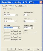
the I:11.1 address that you mentioned is coming from a 1746-NR4 module for RTDs ... the module has four channels which are all set up for 100 ohm Platinum 385-type RTDs ... all of your channels are showing a data reading of "15620" which normally would mean 1562.0 degrees F – but this high reading is undoubtedly caused by the "upscale" setting for a broken input ... were the RTDs connected and "powered up" when this program was last saved? ...

the N140:42 location that you asked about is being used in several places in Ladder File #7 as part of the control for O:6/0 which is documented as "st2 htr contactor" ... so this APPEARS to be the contactor which feeds the "Station 2 Heater" ...

there are some other "Comparison" instructions for that same input signal that we'll have to sort out as we move forward ...

suggestion to think about ... since you say you're going to "strip this down" for manual control, why don't you completely junk this program and start from scratch? ... basically just go through and CAREFULLY CONFIRM that all of the field output devices and field input devices have been CORRECTLY documented ... then decide how the operator is going to control the system – and give him enough buttons and indicators to make that control possible ... BE CAREFUL to give the operator some sort of RELIABLE emergency shutdown system which will bring the process to a SAFE condition ... in most cases, an HMI is NOT the best answer for that type of emergency shutdown system ... you need to think that part of the puzzle through before you go much further ...
 
suggestion to think about ... since you say you're going to "strip this down" for manual control, why don't you completely junk this program and start from scratch?

This is what I have been trying to do. My lack of AB experience makes it difficult to know how to disect this program and take only what I need to make this manual.
 
I'll comment on rungs 1-7 of Ladder 7. It seems to repeat for other zones with the same logic. Don't pay any attention to the numbers in the instructions as they don't seem to be from a running system.

1 - N140:2 must be a desired setpoint, possibly from an HMI as, other than this rung, nothing writes to it. This rung checks to see if the entry to N140:2 was greater than 2500 (some fatfingered operator maybe?). If it is it limits it to 2500.

2 - If 'Heat Enable - B41:0/0 - is on then create a lower 'Deadband Limit' - N140:4. It's lower by 20

3 - If 'Heat Enable' is on start the Dryer Blower

4 - Get the current temperature from the input module (RTD?) and store it in N140:42.

5 - This is your basic control rung. If 'Heat Enable' is on and the current temperature is less than the lower 'Deadband Limit' then start the heater. (The other safety conditions are - the blower has been commanded on, the auxilary contact confirms that and the system isn't in overtemp (probably not needed here as neither of the parallel rungs would be on if that were true)). The lower branch, once the output is turned on, continues the heater until the setpoint is reached. The heater will then turn off and won't come back on until the system has cooled to the lower 'Deadband Limit'

6 - This creates an 'overtemp' setting at 50 over the setpoint.

7 - If the current temperature i greater than the 'Overtemp' established in rung 6 then turn on the 'Over Temp' bit.
 
Last edited:
Correction, with regard to my post #9. It has been pointed out to me that the card is in fact configured. ( see Lad 2-Rung 7) It just is not showing up on the cards config screen.

Thanks to Ron you should be ok with that part of your program.
 
Last edited:
I'll comment on rungs 1-7 of Ladder 7. It seems to repeat for other zones with the same logic. Don't pay any attention to the numbers in the instructions as they don't seem to be from a running system.

1 - N140:2 must be a desired setpoint, possibly from an HMI as, other than this rung, nothing writes to it. This rung checks to see if the entry to N140:2 was greater than 2500 (some fatfingered operator maybe?). If it is it limits it to 2500.

2 - If 'Heat Enable - B41:0/0 - is on then create a lower 'Deadband Limit' - N140:4. It's lower by 20

3 - If 'Heat Enable' is on start the Dryer Blower

4 - Get the current temperature from the input module (RTD?) and store it in N140:42.

5 - This is your basic control rung. If 'Heat Enable' is on and the current temperature is less than the lower 'Deadband Limit' then start the heater. (The other safety conditions are - the blower has been commanded on, the auxilary contact confirms that and the system isn't in overtemp (probably not needed here as neither of the parallel rungs would be on if that were true)). The lower branch, once the output is turned on, continues the heater until the setpoint is reached. The heater will then turn off and won't come back on until the system has cooled to the lower 'Deadband Limit'

6 - This creates an 'overtemp' setting at 50 over the setpoint.

7 - If the current temperature i greater than the 'Overtemp' established in rung 6 then turn on the 'Over Temp' bit.
Thank you, this was a lot of help.
 

Similar Topics

Good day. New to slc500 programming, have never programmed it for analog addresses (inputs). The inputs turn-on and off industrial tank heaters. I...
Replies
6
Views
2,352
I cannot add SLC500 analog input tag (I: 8.3) to EZSeries Touch Panel Editor (V 5.3). I used all the listed tag datatype but it all says "Invalid...
Replies
8
Views
140
can the slc500 5/05 send a email and text over Ethernet ?
Replies
3
Views
182
Hello, did anybody know, if there exist an converting cable like the1492-CM1746-M01 (for an 1746-IB16 to an 5069-IB16), for an 1746-HSCE to an...
Replies
3
Views
385
Customer is buying several spare 504 CPU's to have one handy when there's an issue with the ones in operation. Having them on the shelf for years...
Replies
15
Views
2,813
Back
Top Bottom