neeed help setting a encoder up

mer

Member
Join Date
Dec 2009
Location
Asheville nc
Posts
59
hello again gurus i need help setting up a encoder on a direct logic 06 model 06DD2. the encoder is a Accu-coder by Encoder.. part# 725I-0800-r-pu-1-f-n-s-n, the plc i was told it should work with this encoder straight out of the box,, well not so it seems you have to go into data memory and change abunch of settings my problem other than not knowing what im doing is what settings to choose has anyone ever setup the DL/06 with a encoder if so i need some insight on the v-memory settings and what settings to choose here is the pdf i was trying to figure out thanks in advance.
http://www.automationdirect.com/static/manuals/d006userm/appxe.pdf
 
the plc i was told it should work with this encoder straight out of the box

At the best this meant with no extra hardware. Any application needs programming. There are so many ways the high speed inputs can be used some amount of setup must be done to say WHICH of the many uses you choose.

Did you make a choice from the various modes listed in the PDF you provided? Describe the system in which the encoder will be used.
 
yes!!!

At the best this meant with no extra hardware. Any application needs programming. There are so many ways the high speed inputs can be used some amount of setup must be done to say WHICH of the many uses you choose.

Did you make a choice from the various modes listed in the PDF you provided? Describe the system in which the encoder will be used.
yes mode #20 seems to fix ,,what i want is have a set # for 360deg count in forward and if reversed count backwards and at a set# have an output seem simple but not thanks again ...mer
 
the setup

my setup is a block splitter.. block are feed into a splitter where a flight bar then comes into play and pushes the block towards a set of stationary blades the encoder is connected to a shaft which in turn is connected to the flight bar system ...as the block are pushed up to the blades a preset # which i have put in tells the flight bars to stop and splitter blades to split, then reset and to the next cycle...
 
1. It's interesting that you chose an 800 pulse per revolution encoder when you specifically mention '360deg count'. But that's ok.

2. If the encoder is connected that it turns in one direction as the block is pushed forward then in the other as the pusher returns then mode 20 is an excellent choice (see, you've thrown out a great deal of the PDF file already.)

3. Let's look at page E5 for Mode 20. As your encoder is a quadrature type (the -r- part of the part number) you will be using the bottom part of the Mode 20 line. You will hook "+VDC" from the encoder to your +24VDC supply. You will hook "COM" from the encoder to the low side of your 24VDC supply. You will hook "A" to X0 and "B" to X1. Carefully follow the diagram on page E-25 of the PDF.

Get that set up then come back. Unless you just want to read further in the PDF. Don't worry about the 'presets' right now (we may not use them). But you will need something (a switch perhaps?) to say when the pusher is fully retracted and provide a zero point. That will be wiring to X2 as a 'reset'
 
ok i got it set up what format should i use standard (cnt) or (sgnt) in other words if im using x0 and x1 for the signals do i also use'em as the input in the rung for the signal to count and set the counter up as usual...in other words how would you wright the rungs...
xo----------------------------cnt 0
k500
x2--------------------------cnt 0 (rst)

cnt 0------------------------(y0)

dave..

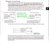
Page 3-29 in the manual. X0 and X1 usually are not entered in the ladder. If the counter counts in the wrong direction, swap the leads going to X0 and X1.

hscount.jpg
 
Thanks Vaughn. Gotta sleep sometime.

Mer - please read the ENTIRE Mode 20 section of the PDF you linked to. It has examples and everything. That's what it's there for.
 
thanks but what do i !!!!1

Page 3-29 in the manual. X0 and X1 usually are not entered in the ladder. If the counter counts in the wrong direction, swap the leads going to X0 and X1.
thanks guys for butting up with me ...i get the enable input and the reset i could use a home switch and make that signal on in the same to enable count and zero counter what i dont under stand is the preload input do i use xo or x1 for this input again thanks abunch i owe you guys for all of yor time..dave..
 
Thanks all!!!!

Thanks guys i figured it out or you guys did for me i should say ...i kept changing the function code for xo-v7634,, for some reasom hex code 1002 (quadrature,absolute)4x countiing worked which makes no sense if someone could explain this i'd be greatfull hex codes are on page e-28 in the above pdf..i posted .mer...
 

Similar Topics

please help I need mmc-oem for mmc103 siemens to create custom pages thank you
Replies
0
Views
1,258
I doing a new project using Mitsubishi PLC Q Series which require to roll up some cable into a drum. I trying few formula to row up to...
Replies
0
Views
4,479
Hi all, hope you are having a great day, I am in need of your help to create a AOI or program that does this kind of job: I have a IO Link...
Replies
0
Views
1
please help me . I have to make this ladder diagram and I can’t figure it out :(
Replies
12
Views
263
Hi Everyone, i was hoping for a little help with this module. i have data that needs to be read from a different plc through the Modbus plus...
Replies
11
Views
188
Back
Top Bottom