Tension and speed control in textile line

Plc_User

Member
Join Date
Dec 2005
Location
Belgium
Posts
317
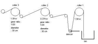
Consider a textile machine with a first roll pulling material from a supply box. After this first roll there is a dancer roll, that the first roll uses to regulate its speed (dancer roll has to be constantly in middle position). After that there is a second roll pulling the material, and after the second roll there is a third roll also pulling the material.
Consider the third roll being master, and operates at a fixed speed and maximum torque is allowd (160% of nominal torque). The second roll pulls from the first roll and also has to create tension between itself and the third roll. To create tension the speed is set 10% slower then the third roll and the tension is regulated by reducing its maximum torque.
Because the master (third roll) has more force then the second roll, the second roll will take up the same speed as the third roll (it will be pulled). I suppose the pull resistance of the second roll will be regulated by the 'regenerative torque'.
If for instance the force the balancer roll puts on the textile between the first and seoond rol is 1000N, the 'regenerative torque' of the second roll is 500N and the 'motoring torque' of the second roll is 3000N, how much will be the torque that the third roll has to pull?
I am a bit confused if the second roll will be a help for the third roll in pulling from the dancer roll because it has to pull the second roll to its own speed, will the second roll deliver all the pulling force for the dancing roll, or will that force be delivered by the third roll exclusively?
 
Torque is in Nm, tension in N - which do you mean ?
These values are just to make the situation, question clearer.
I talk about N because it is the force produced by surface of the roll, thus torque of the motor including the gearbox and diameter of the roll. Main purpose of the question is : how will the system work?
 
The torque on the first roll will be whatever it takes to pull the material out of the bin minus the torque required to maintain the 500 newtons of tension between the first and second roll.

In your design the second roll must always pull back on the third roll. So, assuming no drivetrain or nip losses (which is completely unrealistic) the third roll will be pulling the 500 newtons from the zone between the first and second pull rolls plus the retarding torque developed by the second roll torque limit.

Another way of saying this is that the third roll tangentila force is the sum of the tension between rolls 1 and 2 plus the retarding force from roll 2.

How well this works will depend alot on the drivetrain on roll 2. Large gear ratios take alot of force to backdrive. So if you have a large roll 2 gear ratio you will end up with alot of tension between rolls 2 and 3 even if you have zero torque command on roll 2. Rolls 1 and three are strictly speed controlled so the gearing forces aren't a concern there.

If the know you will always be pulling back with roll 2 why not put a brake on that roll?

Keith
Thanks for your clear answer.
The second roll is drive by a Unidrive SP where you can set a 'motoring torque' and a 'regenerative torque'. I suppose only the 'regenerative torque' will be of importance here?
The second roll has a 0.37Kw motor, the third roll a 1.5 Kw motor. Diameters of the rolls and gear ratio's are comparable (about 1/20, in- and outgoing shafts at 90 degrees).
I am doubting about making the second or the third roll master.
If the second roll were master, it would off course have its maximum torque available, while roll 2 would be reduced in torque and be put higher in speed. The fact that roll 2 has only 0.37Kw worries me to make it master.
You take about putting a brake on roll 2, do you mean some kind of electric brake, what kind (brand) do you have in mind?
 
Is the 3rd roll a winder?

I concur with Keith that a brake on roll two might be a good choice. If there is an intermediate idler between it and the 3rd drive to which you can attach load cells, then use a magnetic particle brake or analog to pressure air brake to control the tension going into the 3rd drive that way.

If the 3rd drive is a winder, then make one of the constant velocity rollers the master.

You don't want to try to use the dancer position to control more than one drive, and you want a smooth velocity and very little dancer movement, correct?

On winding and converting applications I have had the best results when the master speed or line speed was dictated by the PLC and all of the indiviual stations were slaved from this "virtual" axis so to speak. It also makes production planning much more predictable if you line is commanded to make 500' spools at 150' per minute and can accurately do that all day.

Can you sketch the system? Just a side view of the rolls and their positions including the dancer would be sufficient.

Paul
 
The third roll is not a winder, just a pulling roll.
Roll one is not a problem for me, it just pulls the material from the bin, gets a linespeed and requestest position of the dancer. So it follows the line speed and regulates the postion of the dancer. Roller 1 is the only one regulation the dancer position.
Keith has a point I think when he says that when roller 3 is the master and roller 2 a slave that has a lower setpoint and reduced torque, and so will be pulled by roller 3, mainly the resistance of the gearbox will be off importance and there could be high tensions between three and two.
In the tests I already did all rolls had their maximum available torque and the tension between 3 and 2 was set up by giving a little lower speed setpoint to roller 2.
With though material however my roller 3 tripped on high current.Thats why I realised I have to reduce the torque.
My main question for now is it better to make the second roller master, so the third can have a little higher speed setpoint and reduced torque. In this case tension will be effected by the pulling with reduced torque of roller rather then roller two that is pulled and reacts with a reduced torque?
This question could be generalised : to create tension between two rollers that have a gearbox system between motor and roller, is it better to reduce torque of the first or the second roller? Or is regulating motoring torque better then regulating regenerative torque? If the motors were connected directly to the rolls it would not make difference I gues, but maybe the gearboxes (and their size) could make it realy different. Experiences?
Thanks

drawing.JPG
 
Okay, that sketch helps.

You could try making Roller 2 the master running at a fixed speed, and set Roller 3 in torque mode so that it applies a constant torque on the material between rollers 2 and 3. One problem with doing this is that if the physical connection between the rollers goes away (no material or breakage) then roller 3 will accelerate to maximum speed trying to acheive torque. You may not have to deal with this possiblility, but if you do, then you'll need a way to switch between torque mode and velocity mode. This should give better control of the tension on the material than running in velocity mode with a current limit. The other big potential problem is the fact that your 1.5kw motor driving roller 3 will likely win the battle agains the smaller motor driving roller 2, so it would tend to cause roller 2 to go into an overhauling load situation which means regeneration would occur, and that the speed of roller 2 may increase above the desired setpoint. If the tension requirement of the material is low enough with respect to the power applied to rollr 2 then this isn't a big problem.

I still like Keiths idea of turning roller 2 into a braking roller. Do away with the motor and install an I/P transducer and air brake or a magnetic particle brake. If you did this, ideally you could add a load cell to the idler between Roller 2 and Roller 3 and use it to regulate the signal applied to the brake controller. This would keep Roller 3 as the master, and greatly simplify the controls in my opinion. The problem might arise during the threading of the machine, does roller 2 need to be powered for initial threading or for other reasons?
 
I question the size of motor 2. Why 0.37 kw?
What are you trying to do to the material?

I've done a few of these and
Roll 3 was the master
Roll 2 was slave to 3 with ratio trim
Roll 1 was slave to 2 with dancer trim +-10%

I like to have the main ramp function generator in the plc even though Roll 3 is the "master"
 
Sometimes I get myopic and just answer the question that is asked. Fortunately I don't do that much at work. ;)

Textiles (unless you are dealing with Kevlar or something similar) tend to allow for a pretty good amount of stretch. So, as JRW said, you can often get these systems to work with draw ratios between sections. So instead of trying to control torque, control the relative speed beteen rolls 2 and 3. It sounds like you tried this already and you got a fault on drive 3. How much different did you have the speeds set? Even with a textile I would think 1/2% would be about all you want to use.

If you can't get speed control to work for you then it may be better to allow for bidirectional torque control. You just need to change your speed command as you transition from positive torque to negative torque. this will allow you to program in a forward torque bias to try and counteract the drivetrain losses.

Keith
 
I worked on a system that unwound large rolls of rubber coated steel belt materials into a cutting line, and it used the same method you're using. Velocity mode with current limit using messaging to taper the current limit as the roll diameter decreased. This fed into a festoon (dancer bar) through a nip roller which was on the same common DC bus with the unwinder.

In our case the nip roller would fill the festoon very rapidly each time the cutter would index forward up to 12 feet of stock in about 2.5 seconds. The unwinder controlled tension and was set up with full vector control...encoder required...

So it could sit there all day at zero speed with minimal torque current flowing and could therefore react to the sudden demand of a feed to length cutting line that made 14 cuts per minute. The performance was best in torque mode, and we used the PLC to detect runaway conditions. That was more trouble than the messaging and velocity mode with current limit, and its performance was good enough. If it weren't for the number of roll changes and the safety aspects of a 4000lb roll running at 200 rpm, I would have polished my torque mode logic.

The thing I wanted to remember to tell you is that you should seriously look at a common dc bus. That is the most electrically efficient way to handle the regeneration you will be dealing with.

Our cutter was a carbide edge circular blade running on a 50HP dc motor which was also on the common dc bus with the letoff unwinder drives (4 of them) and the nip roller. That blade would pnuematically engage the 30 foot long carbide edged fixed lower blade and zip all the way down cutting the steel fabric at an adjustable angle, retract and return 14 times a minute! So, there was a lot of DC flowing amongst the caps in that motor panel...

That is, unless you decide to make the 2nd roller a brake.

What is missing is tension feedback. Right now, no matter what you do, its open loop control.

Look at Magnetic Power Systems as one example of tension load cells that you can bolt under existing pillow block bearings and get some tension data. They have nice tension control packages as well. We used other brands of load cells too, but I liked the connectors on the MagPowrs and their little blue box torque controllers. We used those to operate their magnetic particle brakes and clutches throughout the plant.

But if the 2nd motor is need to pull product in order to reduce the tension, then keep the motor, but close the loop with a load cell so you can truly measure your progress.
 
I finally set the second roller as master. The third roller
has an adjustable speed ratio to the master (most likely 100-102% of master) and the maximum torque of the third roller can be reduced. By this the customer can do what he wants depending the type of product running on the line, and it works satisfying.
 

Similar Topics

Hi everyone, got a Siemens S7-1200 collecting data off one our furnace lines. I'm getting some interesting activity I'm working on cleaning up in...
Replies
6
Views
699
How do you execute speed or tension calculations in a PLC? Do you use a STI (Periodic task) to make sure the calculations are executed at the same...
Replies
9
Views
4,780
So I'm pretty new around here but I come looking for advice or suggestions to research. Im the plant electrician/SCADA guy for a warer department...
Replies
3
Views
79
I am currently working on a site with a faulty Powerflex 755, we have a replacement but have no access to the parameters with no license for...
Replies
1
Views
149
Hey all, One more Newbie Question I just posted up about the same exact line on a separate problem but I have a challenge that several of us at...
Replies
0
Views
700
Back
Top Bottom