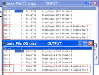
Micrologix 1400 embedded I/O mapping

ltfordnr

Member
Join Date
Aug 2007
Location
seattle
Posts
36
Howdy all,
New to the 1400. I have read the manual a few times (maybe not every word) but still can not find where the embedded discreet inputs are mapped. The expansion modules are easy but where is the embedded stuff? I assumed it would be under inputs and the lower words would be set up as arrays. But nooooooooo they don't seem to be there.
1766-L16AWAA

Thanks:confused:
 
That's what I figured however 500 is complaining that the address must be specified to the word level for what I assume to be bits. I'm cornfused. I also don;t see the embedded outputs in the embedded I/O configuration.
 
That's what I figured however 500 is complaining that the address must be specified to the word level for what I assume to be bits. I'm cornfused. I also don;t see the embedded outputs in the embedded I/O configuration.

User Manual:

http://literature.rockwellautomation.com/idc/groups/literature/documents/um/1766-um001_-en-p.pdf

Instruction Reference:

http://literature.rockwellautomation.com/idc/groups/literature/documents/rm/1766-rm001_-en-p.pdf

Have a look at Page 27 of the Instruction Reference - I/O Addressing. The Embedded I/O is Slot 0 - Word 0 for both Inputs and Outputs.

Try something like I:0.0/0, and see if it likes that better. That should point at Input Slot 0, Word 0, Bit 0.

Stu.....
 
Thanks for the reply but that's exactly the problem.
All indications are that the bit (I:0.0/0 - 20) can be used but logix 500 complains with 'address must be specified to the word level' when I try to access the bit.
 
Ethernet communication between Mico 1400 and Compact

Another question-Ethernet commuunication between the CompactLogix and the Micro 1400 - What message instruction to use - PLC5 tye read and Write or what? I just joined plctalk yesterday and learning how to use this forum but need some answers. You guys have already been a big help.
Thanks
 
Simple Embedded I/O Map:

Here is the embedded I/O map for the 1400 laid out simply:

The 20 Discrete Inputs are addressed by two equivalent schemes:
Inputs 0-19 are I:0.0/0 through I:0.0/19
-or- (as referenced as bits of 16-bit words)
Inputs 0-15 are I:0.0/0 through I:0.0/15
Inputs 16-19 are I:0.1/0 through I:0.1/3

The 4 Analog Inputs are addressed:
Analog Input 0 (IV0) is I:0.4
Analog Input 1 (IV1) is I:0.5
Analog Input 2 (IV2) is I:0.6
Analog Input 3 (IV3) is I:0.7
These are 0-10vdc inputs.
IN CODE: values of 0-4096 equal voltage inputs of 0-10v
For current loop instruments (like 4-20ma) wire a 500ohm 1% resistor between the COM_ANA and the input terminal (IV0, IV1, IV2, IV3). You'll need 1 resistor per input.

The 12 Discrete Outputs are addressed:
Outputs 0-11 are O:0.0/0 through O:0.0/11

The 2 Analog Outputs are addressed:
Analog Output 0 (OV0) is O:0.4
Analog Output 1 (OV1) is O:0.5
These are voltage outputs that range from 0vdc to 10vdc.
IN CODE: values of 0-4096 equals voltage outputs of 0-10v
 
There's more than one way to do it, but my preference for situations like yours is a SLC typed read MSG for both processors.
 

Similar Topics

I have a new Micrologix 1400. I have an SCP instruction that should give me a 0-4095 output on O:0.5 address. Problem is it does not ever change...
Replies
11
Views
2,843
Hello...I'm a pretty fluent SLC 500 programmer, but am now trying to develop a Micrologix 1400 program offline (1766-L32BWAA). I'm amazed that I...
Replies
12
Views
13,102
Hey all, first time poster here. I am wondering if anyone has tried using a Keyence SR-X300 barcode scanner to a Micrologix 1400. Keyence sent...
Replies
0
Views
12
I'm using a SLC typed write from the ControlLogix5572 to the MicroLogix 1400, with path: 2, (MicroLogix IP). The ControlLogix equipment has a...
Replies
0
Views
87
Hi, I am working with a Micrologix 1400 model 1766-L32BXB. With no input wires connected to the “in12” thru “in19”, I am getting 24 volts while...
Replies
4
Views
221
Back
Top Bottom