PLC 5 Test.

jC.

Member
Join Date
Jul 2010
Location
Australia
Posts
26
Hi, I have a whole bunch of PLC 5 gear that needs to be tested before being sent out to clients. I'm very new to PLC's and just need the quickest way to test the inputs and outputs on a whole lot of differernt PLC5 I/O so I can be sure they aren't faulty.
Cheers.
 
welcome to the forum ...

quick questions:

(1) do you have the RSLogix5 software available for testing purposes?

(2) do you have the communications cables available which are necessary to go "online" (communicate) with the processors?

(3) do you already know anything at all about navigating the software to monitor the input bits - and toggle the output bits?

(4) are there any analog input or output modules involved?

(5) what is your deadline on getting this project done? ... please note that "As Soon As Possible" is NOT a valid answer ...

(6) you should also provide us with a COMPLETE list of the full Catalog Numbers from each piece of your equipment ... (for example: processor 1785-L20E/E) ... note that we're not just making you jump through hoops here ... there are MAJOR differences between different types of hardware - and the procedures for testing them do NOT fit into the "one size fits all" category ...

please answer the questions above and we'll be happy to help you proceed ... we hope to hear from you soon ...
 
Last edited:
Thanks and to answer your questions..
(1) do you have the RSLogix5 software available for testing purposes? Yes

(2) do you have the communications cables available which are necessary to go "online" (communicate) with the processors? Yes

(3) do you already know anything at all about navigating the software to monitor the input bits - and toggle the output bits? Yes

(4) are there any analog input or output modules involved? Yes

(5) what is your deadline on getting this project done? There isn't really a deadline, I've got as much time as I want really.

(6) you should also provide us with a COMPLETE list of the full Catalog Numbers from each piece of your equipment ... (for example: processor 1785-L20E/E) ... note that we're not just making you jump through hoops here ... there are MAJOR differences between different types of hardware - and the procedures for testing them do NOT fit into the "one size fits all" category. Ok well there are too many different types to list, but to make it eaiser for you, at the moment on my desk I have a couple of 1771-OBD's and some 1771-IBN's, and I will be using a 1785-L40B Series E in a 1771-A1B Chassis to test the modules.

Thanks.
 
sounds like you've already got a pretty good headstart ... I'm not sure where you're having your problem ... let us know if the following is not what you're looking for ...

here's how I would go about testing the modules you've listed so far ...

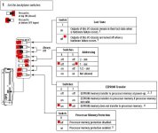
(1) make sure that the chassis DIP switches are set as shown in red in the picture attached ... other settings are possible – but this will be the simplest ...

(2) put the processor into the chassis (in the far left slot) and download a brand new "starter" program with NO control rungs ... go online with the processor ... make sure that the processor is in the RUN mode ...

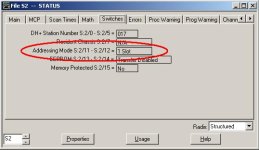
(3) check the Processor Status file and confirm that the addressing mode is set for 1 Slot (as shown in figure below) ...

(4) monitor the Input Data File/Table ...

(5) install a 1771-IBN input module in the next slot (just after the processor) ...

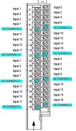
(6) wire up the input module using a 24VDC power supply ... connect the OVDC (return path) to all of the terminals marked in blue ...

(7) as you connect a wire carrying +24VDC (from the DC power supply) to each of the "input" terminals (the ones that do NOT have 0VDC connected to them) the input bits (shown in red) should change from a ZERO status to a ONE status on the Input Data File/Table ... the appropriate LED should also light up on the front of the input module ... note that the module you listed has 32 inputs – so TWO words (two 16-bit "rows") will be involved on the Input Data File/Table ...

survival tip: some "swing arm" terminal strips must have the screws snugged down in order to make electrical contact with the "business end" of the module ... if you leave the screws loose and test by just touching/probing the screw, you might not make electrical contact with the module's circuitry ... specifically, it might look like the input is "bad/open" even though it's perfectly OK ... so ... snug the screws before you probe them ...

(8) put a 1771-OBD output module in the next slot (next after the input module) ...

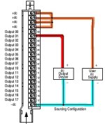
(9) wire up the output module using a 24VDC power supply ... connect the +24VDC to all four screws at the top of the module as shown ... connect the 0VDC (return path) to the bottom screw as shown ...

survival tip: instead of using a voltmeter for testing, use something like a relay with a 24VDC coil ... reason: most transistor/solid-state type output modules have a certain amount of "leakage" current which continues to flow through the output circuit – EVEN WHEN THE OUTPUT IS TURNED OFF ... this current is often high enough to fool a sensitive meter ... specifically, the output might test "ON" – even though it's actually "OFF" ... but ... using a suitable relay coil will "load" the circuit enough to eliminate the false "ON" reading ... also remember to "snug" the screws before testing/probing them ...

(10) connect one side of the relay coil to the 0VDC (return path) as shown highlighted in blue ... now probe each of the "output screws" with a wire connected to the other side of the relay coil – (highlighted in red) ... the relay should energize (ON) when you type a ONE into the appropriate bit/box on the Output Data File/Table (highlighted in yellow) ... the relay should de-energize (OFF) when you type a ZERO into the appropriate bit/box ... note that you do NOT need to program in any control rungs to "turn on" the outputs ... just manually typing ONEs and ZEROs into the bit/boxes will be sufficient for a test ... you also do not need to "Force" the outputs on and off ...

(11) as you test each output, also confirm that the appropriate LED lights up on the front of the output module ...

see if this is enough to get you going ... I apologize in advance for the inevitable typographical errors ... it's late – and I'm tired ... there are plenty of other forum members who can straighten out any mistakes I've made ... hopefully this will make a good "first draft" ...

another quick question for you: do you understand Block Transfer Read and Block Transfer Write operations? ... you'll need them for testing the analog modules ...

good luck with your project ...
OBD_WIRING.JPG IBN_WIRING.JPG CHASSIS_DIPS.JPG ONE_SLOT.JPG IO_MONITOR_TOGGLE.jpg
 
Last edited:
For quite a bit of your testing you can remove the IO cards from the chassis (power down before unplugging any cards) and then simulate inputs by toggling the bits in the IO image table or in the PLC program with the processor in RUN.

The PLC/5 contains an input/output image table that covers its full range of IO - it doesn't have to have a card actually plugged in to use an IO address in its program. Testing any parts of your program that use Analog IO will be a little more difficult but you can still do it the same way.
 
Greetings Alaric ...

my interpretation was that he's just trying to test the I/O "MODULES" (specifically, the hardware) and not any particular programming code ...

let's see what he says when he comes back again ...
 
Thanks for the reply Ron, I've just gotten back into work after the weekend, and am about to do what you've said, and yes I'm just looking to test the hardware, no programming code. I'll get back to you and let you know how I went with what you've said to do, thanks.
 

Similar Topics

See code at the bottom. Hi all. For the story, this is my first complete project using a Rockwell PLC, I've been mostly working with Unity Pro...
Replies
7
Views
792
Hey Guys, I am looking to bring some new guys onto my team and I was pondering the idea of doing a basic test just to weed out some peoeple that...
Replies
17
Views
2,810
Hello everyone I have a Siemens S7-300 CPU 315-2DP, CP343-2P and ASI module .AC2459 I want to using it for test input output . as show in below...
Replies
18
Views
4,268
Hi All, Im looking for an off the shelf product that generates test sheets from templates that easy to manage with an easy to use interface. We...
Replies
5
Views
2,432
so im trying to test something with a PLC attached to my laptop thats mounted on a board with some lights and switches, but im having no luck and...
Replies
16
Views
6,292
Back
Top Bottom