Flying Shear Accuracy Issue

69FIREBIRD

Member
Join Date
Oct 2004
Location
New Zealand
Posts
102
Hi All, I have been asked to look at a flying shear tube mill and improve on its accuracy currently running at up to +/- 3mm and needs to get down to a consistent +/- 1mm. Current hardware is a 1756-L60M03SE processor/sercos interface, M02AE MO2E & Ultra 3000 DSD-HV150-SE drive.

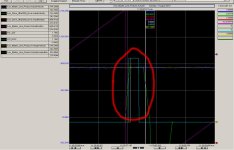
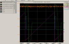
Could I get some feedback on the trend I have compiled. When I review it I see the slave (shear) “actual” velocity overshooting the master “actual” velocity, the master “actual” velocity “flicking” up and down, and the slave “actual” position lagging the master position. Is “actual” the correct thing to be trending to get a true representation of what is happening or should I be looking at “average”

The "CUT_NOW" and the "SOL _235" are the respective cut control logic and pneumatic cut solenoid – which trends a consistent electro/mechanical/pneumatic interval time – so I’m not suspecting that as an issue in respect to the accuracy. To me there looks to be a requirement to tune things up to improve the accuracy.

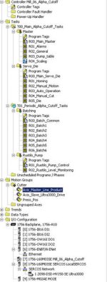
I note that the the majority of the program is built in the continuous task folder with several low level perodic taks for minor aux control/interfacing and question whether it should be grouped into periodic and event based tasks.

I’ve started wading through some of the manuals – but I’m on the step part of the learning curve at the moment.

I’d be interested in your thoughts and directions options I can take to improve the accuracy of this system.


Thanks.
Motion Trend1.jpg Logic Task Layout1.jpg
 
Good graph, it provides lots of info.

Could I get some feedback on the trend I have compiled. When I review it I see the slave (shear) “actual” velocity overshooting the master “actual” velocity, the master “actual” velocity “flicking” up and down, and the slave “actual” position lagging the master position.
The over shooting isn't that bad IF it always happens the same way but it doesn't look like it does.

Is “actual” the correct thing to be trending to get a true representation of what is happening or should I be looking at “average”
You want to be graphing the actual position and velocity just as you are doing.

The "CUT_NOW" and the "SOL _235" are the respective cut control logic and pneumatic cut solenoid – which trends a consistent electro/mechanical/pneumatic interval time – so I’m not suspecting that as an issue in respect to the accuracy. To me there looks to be a requirement to tune things up to improve the accuracy.
Perhaps if you gave the velocity more time to steady out after the overshoot.

I note that the the majority of the program is built in the continuous task folder with several low level perodic taks for minor aux control/interfacing and question whether it should be grouped into periodic and event based tasks.
So what motion commands are you using? A long time ago I thought cams were used.

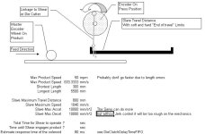
Things l like to know are the cut length, I estimate it to long, about 4 meters. The travel distance of the shear. This looks short maybe a half meter. The shear cut time. This looks like it is only about 0.15 seconds which is fast.

You can try slowing down the acceleration and deceleration unless you need to accelerate that fast due to a short travel distance for the shear. Reducing the acceleration would reduce the over shoot.

The lagging is not a problem as long as the lag is consistent. Lagging is only a problem if you must cut at a specific position or mark on the product. If you are just cutting to length then as long as the errors are consistent the cut lengths will be the same.

I like to program these so that the acceleration is just fast enough to get back in time. This way I don't beat up the machine and more than necessary. It looks like your system is accelerating to 937.5 mm/sec in about 0.1 sec or about 1 g.

About the lag. I think this is happening because the shear and line positions are both zero when the shear starts. The slave needs to ramp up to match the line speed so it will move only half the distance the line speed does and that is why it lags. If you need to have both the slave and the master synchronized at the same point the start point for the master must be two times slave ramp distance from the synchronization position.
 
Hi Peter,

It looks like the synchronising is done with camming instructions.

Standard length is 5.5m and there is batch logic / HMI interfacing to allow various batches to be run one after the other. i.e. 100 qty @ 2.0m then 250 qty @ 4.5m once all batches are complete then it reverts back to standard length 5.5m

The travel distance is approx 450mm at a line speed of 40-50m per min.

The shear time is approx 0.3 seconds.

Thanks for the feedback.

I'm experimenting with delaying the actual knife clutch firing but am working through timing / production speed issues - if I delay things that sort my accuracy issues - then I have issues with line speed and production volume that the customer wont be entirely happy with.

Motion Trend2.jpg
 
Rockwell Detail Questions

as Peter said you are close to the limit

some simple timing facts 50 mpm = 833.3mm/s = 0.833 mm/ millisecond
so you are looking for consistency at the 2 ms range or better
Check input assumptions
  • The Master Axis is a MO2AE - What are the counts per mm?
  • you will need absolute minimum of 10 counts per mm I would aim for a minimum of 100 and try for the max possible (The MO2AE can take a 4Mhz input)
  • The Master Speed jumping about implies that the scaling is coarse at the rates you are looking at
  • How is the Master encoder Physically connected - encoder on the product? attached to the feed drive? Can the feed system slip on the product?
Processor Base Timing
1) What is the Coarse Update Period of the Motion Group?
2) Existing Tasks continuous task (T00_Main...) and the periodic (T01_Periodic...)
  • What is the monitored Scan Time of the task?
  • What is the Interval Time of the task?
  • Are you getting any task overlaps?

Ultra 3000 Axis Setup
  • Motion Planner ->Master Delay Compensation On/Off
  • Motion Planner -> Master Position Filter On/Off
  • Dynamics -> Max Speed and Max Accel and Decel
  • Gains -> Velocity feed forward and Accel Feedforward
  • Limits - > Peak Torque/Force Limit
What does the "press position" Axis do ?
Master Axis Setup
  • Conversion-> Conversion Constant with units

Software Versions in use - Firmware in use is it the latest for the software?

Cutoff Program Control - Two methods exist
Please look for a MAPC in the code or a MAG in the Code - Which is it?
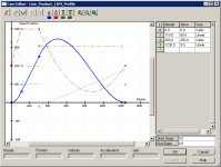
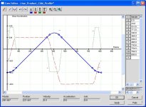
If the MAPC exists then press the [...] button next to "CAM profile" and provide a screen dump
From the chart you provided it is Highly unlikely they are using Jerk Control which could be part of the cause in the speed overshoot - the other is probably an autotune with a damping factor of 0.8

What is causing the Master Axis to Reset to 0 - please paste a program snippet so we can see if some accuracy is being lost here.

The Return Stroke - I'm with Peter here why so rough on the mechanics when you have ages to get back - also the return profile looks the same as the out profile Very High Accel and a slightly less Decel rate - someone was lazy setting this up

Can you redo a chart using 3 ms or 2 ms sample rate - and only provide the Cut and return Move - Did you know that you can export the chart to CSV (Stop the Trend goto LOG -> "save trend log as ..." then zip it and post it? (gets us the scaling of the other trend pens. Warning - This MAY overload your processor.

oops - I just looked at your web site, you are doing this for a client - probably gave too much away ohh well
 
Hi Michael,

*The Master Axis is a MO2AE counts per mm = 17.066666 ((PPR x4) / wheel circumference = 2048 x 4 / 480mm = 17.06666667) The encoder is a SICK programmale unit so I can look at ammending it's PPR.

T*he encoder is directly linked to a wheel (480mm circumferance) that is in contact with the tube running into the shear section. the contact between the tube and wheel is purely friction based and has clamping devices to hold the tube securlely against the wheel. I had noticed a vibration at this encoder point and a shudder when the knife cuts.

*What is the Coarse Update Period of the Motion Group = 2.0mS
*Existing Tasks continuous task (T00_Main...) = GSV of LastScanTime = 2.3
*The periodic (T01_Periodic...) mS = Set for 10mS
*Are you getting any task overlaps? = need to check

*Motion Planner ->Master Delay Compensation On/Off = Ticked
*Motion Planner -> Master Position Filter On/Off = Ticked
*Dynamics -> Max Speed = 1040.5294 mm/s^2 and Max Accel = 95955.29 mm/s^2 and Decel = 95955.29 mm/s^2
*Gains -> Velocity feed forward = 100% and Accel Feedforward = 100%
*Limits - > Peak Torque/Force Limit = 292.6207%

The press position is the rotory position of the shear via encoder feedback.

*Conversion-> Conversion Constant with units = 17.066666 Feedback counts /1.0mm

*Software Versions in use Firmware in use = 15.5

*Cutoff Program Control = MAPC

*MAPC exists then press the [...] button next to "CAM profile" and provide a screen dump = Attached.

*Autotune ?

*please paste a program snippet so we can see if some accuracy is being lost here = full program attached

*The Return Stroke - I'm with Peter here why so rough on the mechanics when you have ages to get back - also the return profile looks the same as the out profile Very High Accel and a slightly less Decel rate - someone was lazy setting this up = The shear cuts down to 300mm we added a MAM back to 0 to get it home ASAP for the next 300mm length.

*Can you redo a chart using 3 ms or 2 ms sample rate - and only provide the Cut and return Move - Did you know that you can export the chart to CSV (Stop the Trend goto LOG -> "save trend log as ..." then zip it and post it? (gets us the scaling of the other trend pens. Warning - This MAY overload your processor. = can look at doing tomorrow (4/8/2010)


Cam1.jpg
 
Hi 69Firebird:

My guess is that your retrofit is an Alpha cutoff from thermatool. I did the same about four years ago, in my case our system worked with a hidraulic cylinder and a servo valve instead of a servo drive, by the way you can look for my thread at that time. I received great help from many people specially from peter nachtwey. Thanks Peter.
My two cents are only related to how fast you cut must take place, in my case i used event tasks, one to cut and other to finish cut and send the die set back home. (Task_corte and task_fin_corte ). Our system is working at 90 meters per minute with a +/- 1 mm of precision. Our pipe ranges are from 4 up to six meters long. pipes.

alpha.jpg
 
Last edited:
Oh Me and my big mouth

Firebird

A list of things on a quick look through:
  • This is the programmers first program that uses CAM's (MAPC), I see leftover code from using MAG in the program
  • The CAM in use has speed turning points causing the overshoots
  • The Auto Tune of the Axis was done at 25% of max speed - I usually use a minimum of 60% and sometimes reduce the Torque to 80%.
  • The soft ware limits imply that you have up to 960mm of slave travel ? please check
  • You have a Hydraulic Solenoid connecting to a Flywheel - speed Timing issue here
  • You are comparing ActualPosition's throughout the program and they can change during the program scan - look at the help for MSGP (Motion Group Strobe Position) instruction (Asynchronous update again)
  • on the Slave Axis the Master Position Filter is 4 Hz - lookup what it does to MAPC and MAG.
  • The CAM is recalculated every cycle based on the current speed - This makes commissioning the MAPC harder.

Some ideas to improve the system
1) Master reference - get it smoother in speed do the maths to get the maximum possible counts per mm
2) Learn More about how the MAOC operates - Especially Postion and enable and that you can use OTU at the same time as the MAOC. Also the Master Compensation.
3) Turn Off the output processing on the periodic task (you are already doing it on the continuous task)
4) Get the Shear to stop at the same physical position Every Time even after power on (look at the MAH on the marker with a Engineering Offset that changes if the encoder is replaced)
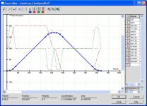
5) Rethink the CAM. Need Smoother (continuous Accel rate) and it only changes if the product length changes - see attachment for sample.
6) Retuning the Ultra 3000 may also assist
7) Create some logic (so that you can trend) that captures the Master and slave position's (and the difference) when the physical cut occurs eg flywheel position. I expect the difference to be your +/- 3 mm - Now you can see if what you are doing improves the accuracy.

Please verify that the flying shear diagram is correct especially the total possible travel length (Peter and I can help you determine maximum line speed based on cut length later I.e. on short lengths you may have to slow down)
BetterCAM.JPG

Flying Shear.JPG
 
That is a much better motion profile but...

However, you can save a few milliseconds at around 450mm. Why decelerate to a stop and then start again? You can see there are two deceleration ramps when there should be just one. The time between the two negative accelerations is not wasted. The distance required to turn around goes down a bit, not by much but F69Firebird needs all the tricks.

I don't ramp to a stop when coming back.

I would get much higher count encoders. Look at 69Firebird's graph. The ability to measure velocity is rough and it could be finer. This allows for much higher derivative gains that allow for damping and reduced over shoot. At max line speed you should have about 3 million counts/sec. You don't want to get too close to the 4 million cps because a little jitter will cause a fault.

I usually tune the system to be critically damped instead of having a damping factor of 0.8. There are always going to be some errors in estimating the model so in reality the damping factor is about 0.95 to 1.05 but that is better than being as low as 0.75.

I haven't played with AB's motion control for a while but I assume things haven't changed too much. I think 69Firebird is up against the limit of what the PLC and M02AE can shuffle position data back and forth. There are a lot of little asynchronous things that must happen to get the encoder data to the PLC and then send the coarse position back to the M02AE. At about 1 m/s the axis travels 1mm in 1 milliseconds. This is where being able to compare the line encoder to the shear position immediately within the same scan makes a big difference.
 
you can save a few milliseconds at around 450mm
Yes I can, I was playing with the better profile but couldn't get it to work the way I wanted so posted the other.

I haven't played with AB's motion control for a while
The L73 processor (out this year) is better than the L60 Processors which are much better than the L55 but still no patch on a true Motion controller

The MO2AE in this application are all feedback only axes no control.
The SERCOS is the only one that needs the coarse update (I just looked, the Sercos link rate is 2 ms - I would have used 0.5 ms)

limit of what the PLC and M02AE can shuffle position
The PLC Code has holes in it that are not helping either

BetterCAM2.JPG
 
That motion profile is better. This isn't suppose to be one that works for 69Firebird is it?
Using s-curves is much better but there is a cost. Since the average acceleration with the s-curves must match the linear ramp acceleration rate the peak acceleration will be much higher than the average.

The SERCOS is the only one that needs the coarse update (I just looked, the Sercos link rate is 2 ms - I would have used 0.5 ms)
Yes, but that doesn't solve what I think is the main problems:
1. Calculating accurate speeds from the line encoder. This is critical to calculating accurate derivative terms for the shear. The velocity feed forward it set to 100% which is right. I have doubts about the acceleration feed forward value at 100%. 100% of what? The difference in gains between the velocity feed forward and the acceleration feed forward depends on the time constant of the system or bandwidth.

2. There is a time delay between the line speed encoder reading and the coarse update to the Sercos drives.

While we are waiting for 69FireBird to get back to us, I am going to try this on my system. We take a slightly different approach. We don't need cam tables.
 
Just asking a silly question but why doesn't the actual velocity profile on the return move look anything like the expected velocity profile from the CamBuilder? Also, since this is a cammed move all the way, why is the forward steady state velocity during the cut so variable but the return velocity is so smooth?

Keith
 

Similar Topics

Hi All, I Have a question, I am very thank full to you if help me, I designed a flying shear controller based on fpga and microcontroller, but...
Replies
20
Views
4,410
I'm working on a flying shear application consisting of two kinetix 350 drives. I need to find a way to connect the encoder connected to the...
Replies
6
Views
2,798
Here is a nice flying shear application. This type of project is often asked about here...
Replies
2
Views
3,440
Hi, I'm new to PLC's...more of a PC and Labview person for 20 years...Question to you pros out there...We're building a flying shear machine (I...
Replies
2
Views
3,589
Hi.. I have flying shear application using rotary knife. The line speed is 100 FPM and rotary knife using Vector motor with Inverter for speed...
Replies
5
Views
6,457
Back
Top Bottom