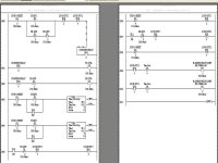
help me with this one

alex_cordova

Member
Join Date
Oct 2009
Location
paramount
Posts
102
here it is:

i have been on this project for days

i need to write code for 2 motors, 2 flashing fault lights and 4 inputs thats it , no more!!!!! this is for school!! Here is the scope.

Write the PLC logic so that if the system is stopped both motors will stop and if either motor trips an overload a pilot light will flash on and off to indicate which motor has faulted.The lights will continue to flash and disallow the system from being started even after the overload has been reset. Pressing the stop button should reset the system and allow the motors to start back up when the start button is pressed.

I:0/0 stop/reset button
I:0/1 start button
I:0/2 M1 aux coil
I:0/3 M2 aux coil
O:0/0 m1 coil
O:0/1 m2 coil
O:0/2 flashing fault light over load m1 coil
O:0/3 flashing fault light over load m2 coil
this program is easy using other contacts, like the ones on the starter that are normally closed which are 5 and 6 or the ones that come with the solid state over load for allen bradly which are the normally open contacs 97-98.

But my instructor said to write code only using the holding contacts which have terminals numbers marked 2 and 3 on the starters thats it!!!

OK i did , and everything is fine , but i have one problem!

if m1 coil is still triped when i hit the start button, m2 coil wont come on at all and fault light will come on fast saying m1 coil is still faulted which is fine

here is the problem when its the other way around, if m2 is still tripped by overloads, M1 coil will kick it for about 1/4 of a second then drop out becuase m2 coil is in fault condition, i have tried very hard to fix this for days but i cant is this possible.
 
Last edited:
If you are using an AB programming package it creates an RSS file. Zip that file then attached the zipped file to your next post.

If you aren't using an AB programming package but can print your ladder logic download CutePDF or some other PDF-Printer emulator. Then 'print' to a PDF file and post that.

Either of these is better than a picture which are frequently unreadable.
 
every thing is fine , i just have that one problem,
if m1 is still in over load condition then m2 will never start, and i will get a fault saying m1 coil is still in fault ver fast, but the other way around, if m2 coil is still in fault condition, m1 coil will start for about 1/4 sec and drop, and ill get a fault saying that m2 is still in fault, iam trying very hard for that not to happen,

is this possible ???????????
 
Your reset does not check that the overloads are reset, so it just resets the lock-out alarm bits.

These bits do not come on immediately on restart, you delay them.

On starting, M1 comes on straight away and M2 depends on M1.

So the M1 coil is always energised when you restart, but after your delay it sets the lock-out.

So when you overload M2, on restart M1 will run until the timer times out as M2 is still overloaded, the output will probably come on for M2 but I presume a N/C contact from the overload is in series with the coil.

When you overload M1, M2 cannot come on as M1 cannot energise, but the output for M1 will come on.
 
i am sorry if i wrote my last reply wrong.

1. If m1 is in over load, but m2 coil is not , start button is pressed and m2 coil will start and dop because of over load on m1. <<<< i do not want m2 coil not to start at all and go in to fault condition<<< this is un safe becuase the m2 coil starts and could drive the motor

2. if m2 is in over load, but m1 coil is not, start button is pressed and m1 will not start at all because of fault condition on m2 coil.<<< this is good, perfect!!!

i do the timer thing because if i don't , they first fault rung will be true , because of the fast scan , so i kind of delay it.
 
Last edited:
i am sorry if i wrote my last reply wrong.

1. If m1 is in over load, but m2 coil is not , start button is pressed and m2 coil will start and dop because of over load on m1. <<<< i do not want m2 coil not to start at all and go in to fault condition<<< this is un safe becuase the m2 coil starts and could drive the motor

2. if m2 is in over load, but m1 coil is not, start button is pressed and m1 will not start at all because of fault condition on m2 coil.<<< this is good, perfect!!!

i do the timer thing because if i don't , they first fault rung will be true , because of the fast scan , so i kind of delay it.


OK, you had it the other way around in the previous post and the original post.

I was thinking overload input but I presume the aux input is feedback from the coil, is that correct?
 
every thing is fine , i just have that one problem,
if m1 is still in over load condition then m2 will never start, and i will get a fault saying m1 coil is still in fault ver fast, but the other way around, if m2 coil is still in fault condition, m1 coil will start for about 1/4 sec and drop, and ill get a fault saying that m2 is still in fault, iam trying very hard for that not to happen,

is this possible ???????????

No :)
 
Let's think about this.

You are determining an overload condition by trying to start then, if the contactor's auxiliary contact doesn't close within a certain amount of time, you have an overload.

When you press the stop/reset button these determinations are lost and it takes the minimum time to determine it again.

Assuming that the contactor's coils are wired through the normally closed contact of the overload it is safe to actually restart except that, if only one is overloaded, the other can start, except in your case tested in rung 2 where if #1 doesn't close then #2 won't try to start. (You obviously can't use this on both since nothing would ever start.)

The code doesn't know if the system is REALLY overloaded since a set of overload contacts aren't brought back to the PLC.

If you can't use real overload contacts then the only recourse is to try to start and, if that fails, declare an overload again. This is really a no-win situation. If a real-world system will have a problem by the momentary attempt to start then it must be rewired. You can't cleverly program to get information (actually overloaded) that isn't directly presented.

If another set of NC contacts are available on the overloads then wire the 'Stop/Reset' button through them in series before getting to the PLC. Then both overloads must be reset to allow resetting the overload condition and permit starting.
 

Similar Topics

Hi all, hope you are having a great day, I am in need of your help to create a AOI or program that does this kind of job: I have a IO Link...
Replies
0
Views
41
please help me . I have to make this ladder diagram and I can’t figure it out :(
Replies
12
Views
290
Hi Everyone, i was hoping for a little help with this module. i have data that needs to be read from a different plc through the Modbus plus...
Replies
11
Views
203
Hello, I am trying to replicate a piece of logic on the PLC5 onto an SEL RTAC. I am using ladder on SEL and FBD. I am having issue on the ladder...
Replies
13
Views
217
Back
Top Bottom