What instruction to use to read data from encoder?

bornwild

Member
Join Date
May 2010
Location
Riyadh
Posts
429
I am new to plcs. I am just wondering how data is read from the encoder for controllogix AB PLCS. Also, can some explain about Bitfield distribute instruction. Rslogix help instrction didnt help me much as i still didnt get it.Also,do we use same process for both absolute and incremental encoders.One last question suppose we replace the encoder with a new one do we have to reconfigure it or is it like plug and play. Looking forward for good replies. Thanks
 
That depends on what plc´s or what platform you are talking about.
1746-hsc(e) for slc500, 1769-hsc for ML1500 and compactlogix, 1756-hsc for controllogix, ML1100 etc.
Please tell us what is your module and plc model.
 
That is still not nearly enough information.

How is the encoder connected to the controllogix system?

Often, absolute encoders are connected to standard DC input cards using up to 16 points and the value of all the relevant points are read at once as a decimal (binary) value. The absolute encoder will do the counting for you and simply send the number in binary using multiple wires. With controllogix, it may be required to use the CPS command to get a snapshot of the whole value while preventing the input card from changing any of the bits during the copy.

Incremental encoders are usually wired to high speed counter cards using only a few wires since they just send pulses and the card itself must do the counting.

What is the mfg/part number for the encoder?
 
not at work atm. But generally how do you program them.I have sick encoder. Dont have the part number atm.It had around 8 wires coming out of the encoder
 
Last edited:
I dont know how it is wired. But we use bit field distribute instruction. I went to instruction help but didn't seem to understand clearly.
 
via PM, bornwild is still having problems understanding the BTD instruction.

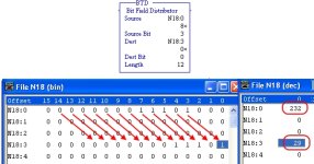
This instruction is used to copy a group of bits from one word (or group of words) to another area, while changing their locations within the group.

Suppose you wired a 12-bit absolute encoder to an input card, but the first three inputs were already taken, so you wired it to inputs 3 through 14, with point 3 being the least significant bit.

Now when the encoder is sending a binary "1", input point 3 will be on and points 4 through 14 will be off.

If you mask out the first three bits which aren't part of the data, the value you will see is 8, so how do you get it to read 1? You could bit shift three times, or do some math, (after you used MVM to block the first three bits), but the BTD can take care of both of those operations for you by only copying the group of bits you're concerned with:

BTD_000.jpg
 

Similar Topics

Hi All. I can write an N7 value to a modbus register in an Automation Direct Servo but I can't read a holding register to an N7 address. I've...
Replies
3
Views
1,898
Lately, I've been using Modbus for reading sensor values in process programming. I haven't used Modbus much, so I spent some time looking at...
Replies
4
Views
1,883
Hello, I have a radio telemetry system that has an RS-232 interface that "understands" the DF1 protocol. In one place I still have a Compact...
Replies
4
Views
2,102
I programmed a couple of MSG instruction for a PLC5/80E to write and read data to a SLC 5/05 thru an Ethernet network on non-continuous mode. It...
Replies
1
Views
2,493
All, We are developing MSG instructions with ControlLogix; this controller is the master data collector for the plant. However there are some...
Replies
10
Views
4,463
Back
Top Bottom