PLC Controlled greenhouse

northpad

Member
Join Date
Aug 2010
Location
Eugene
Posts
21
Hey all, I have an organic greenhouse on my property and wish to automate it as much as I can. So, if at all possible could anyone help me figure out what I would need to buy and maybe some help walking me through the setup.

Here is how I see the setup looking:
Outputs need:
3 - 240v each output will have a max draw of 5 amps, on a timer
1 - 240v for water pump 0.5 amps that is on a timer
1 - 120v for exhaust fan 1 0.8 amps that is on a timer
1 - 120v for exhaust fan 2 0.8 amps that is on a timer
1 - 120v for water pump ~0.5 amps that is running full time
1 - 120v this output would be powering a water chiller
1 - 120v dehumidifier that will turn on/off to maintain humidity
1 - 120v CO2 generator
1 - 120v A/C unit 5.5 amps
1 - 120v PH pump

There may be a need to expand the number of outputs, 240v and or 120v.
I have a sub-panel with a 100 amp main circuit

2 - 30 amps 240v circuits
3 - 15 amps 120v circuits
So power is not a problem.

I also need some inputs.
1 - humidity sensor
1 - room temp sensor, maybe 2 sensors that give an average temp of the greenhouse
1 - Co2 sensor
1 - water temp sensor
1 - PH sensor
1 - Conductivity sensor
1 - water level sensor
2 - Air temp sensor

I know it may sound complex but organic farming is very time consuming. The more control I have over my environment the better. That is why I have to monitor so many things. I have it running now using cobbled together sensors, timers and plugs. I know a system like this will cost some cash, but it is an investment in my business. The reliability, expandability, and versatility of a PLC makes it sound like a winner. I have looked into some great little PLC system that would make the wiring of the system rather easy.

http://www.eaton.com/EatonCom/Market...lays/index.htm

I have been looking at the 700 or 800 EZsoft Controllers from Eaton. They have a lot of input/outputs, if you get the EZ expansion mods. I know there are other way to do it but using the Eaton controllers would be simpler. In the end, I need to have ability to monitor the environmental sensors in real time, with a PC. The programing will be a whole other posting, but first I need to find out what hardware I need, and all that good stuff. Well I hope to hear from someone.
 
Last edited:
First thing I see is the amp draw of your first three outputs will require relays. No big deal, they will increase your plc reliability. PLC output can be low amperage to energize a relay coil, the relay will switch the 240 volts @ 5 amps. Since the rest of your outputs are 120v you could use a 120v output module for everything and then use relays for the 240v devices (first four in your list).

Whoops! almost missed the "1 - 120v A/C unit 5.5 amps". That one needs a relay also.

If it were me I'd use relays for everything - all outputs. It will increase the plc output lifespan. Relays are much cheaper than a new output module. Your exhaust fans are not something you want a plc output turning on directly so I think a plan to install relays for each output is a good idea.

As for your choice of controller I don't have any advice other than if your local support for it is good, then it may be the right one for you. With PLC's the support you receive locally often dictates what brand you use.

Good Luck!
 
northpad,

Your application is not a big deal. Think of it as eating the proverbial elephant....One issue at a time.

If you know PLC, then think one rung per deliverable objective (Output) and go as far down the list as possible. If you don't, then you have come to the right place.

Start at the beginning and ask a question. We have our own projects but we'll find time to help you with yours.

As for the heavy loads, the solution mentioned by Paul B, is called "interposing relays". The PLC controls the relay coils, and the relay contacts control the loads. As much as possible, use ones that have a visable indicator so that you can tell at a glance when they are energized. This makes troubeshooting much easier.

As for I/O count, a "lot" would be 5000, 25 is a nap. The issue is that 25 is a bit more than the most simple PLCs. Currently, I'm using AB MicroLogix 1100 for jobs like yours.

Equipment selection is a matter of risk vs reward. You need to figure out how much it is worth to you and then get the easiest system for the money.

There are serious systems, then there is cheaper stuff that some think are serious, and then there are some borderline toys that some also think are serious.

Choose where you can get the required support, because the effort down the line will be markedly different between the various systems. As an example, there is someone in every county that knows the serious stuff and there is one guy in each state who knows the toys. So pick your poison accordingly.

Also, one last titbit, I have worked on irrigation systems and it is not a good idea to treat an automation system like a piece of garden hose, which is not that uncommon. Think about the environment where your other prised electronic systems reside(TV, Radio, Microwave) and design accordingly. Dust proof is not the same protection as hose down, etc.

Best Regards,

Bob A
 
You might want to look at a CMP-6050 controller contact [email protected]

This is a dedicated environmental control unit designed for growth chambers. it has the capability of doing most if not all of what you asked for right out of the box just program your parameters
 
The relays for your motor loads will need to be at least power relays being inductive loads. Relay specs show different max loads for contacts for DC and inductive loads. Make sure your relays are rated higher than the load of the motors. Also, you may want to individually fuse the power to the motors.
I'm imagining that all of this gear will go in some kind of enclosure. Being a humid environment, the enclosure should be rated TYPE 4 at least, if not 4X. I would get a fiberglass or FRP enclosure.
Put surge protectin on the incoming power.
 
1. First, get the system working using a relay control cabinet and manual On/Off switches. As others said, first build a relay control box, with switches on the front that turns the various devies on/off using relays mounted in the cabinet. For safety around wet environment, I suggest using 24 volt DC relay coils with 10 Amp contacts rated for motor starting duty at 240 volts AC. Because your pumps and equipment is 120 and 240 volts does not mean that your sensors, relays, and PLC cannot operate from 24 volts DC. You will need a cheap 120 AC-to-24 VDC power supply.

2. Then, as your PLC knowledge progresses, add a 24 volt DC PLC cabinet, and wire your PLC outputs in parallel with the manual switches, with PLC outputs that send power to the relay coils. If your PLC fails, you can still control your system manually.

3. The water pump that runs all the time does not need PLC control, unless you DO want to turn it off AUTOMATICALLY at rare times. Also, I see no benefit to control the water chiller, dehumidifier, and air conditioner with a PLC. The PLC cannot add any benefits to the normal controls for these devices, UNLESS you need a master control to shut down everything at the same time.

4. Speaking as a former greenhouse owner (small one!), if you truly want to automate your greenhouse control, then do not use timers to control when your plants are watered. Instead use moisture sensors. Plants may need more or less water at different stages of growth, and for varying amounts of sunlight and heat in the greenhouse. You will find that you will have to continually adjust the watering timers nearly every week, but some simple moisture sensor switches embedded in the soil at typical spots will be more accurate. You can still use PLC program timers to set minimum and maximum watering time limits so that plants are not overwatered when sensors stick or fail. Again, use 24 volt DC sensors and 24 volt DC PLC inputs for safety.
 
Last edited:
One thought that I would add to the plan advanced by Lancie1 is that I'm not too comfortable using the PLC output in parallel with an on-off switch. This brings external power to the output screw when the PLC is trying to turn it off from the inside.

To avoid this, I would suggest a Manual Auto Switch that applies power to the manual switches in Manual and to the PLC I/O in Auto Mode (One Switch Method). Or you could have an Manual Auto for each output if you would want to select individual outputs for manual or auto control.

Technically, the statement that:
"If your PLC fails, you can still control your system manually." may not be entirely true. If the output of the PLC shorts (fails on), then the switch would not be able to turn the output off.


Best Regards,

Bob A.
 
This brings external power to the output screw when the PLC is trying to turn it off from the inside.
If wired correctly, you will have only the same power at the PLC common terminal as you would have if you did not use the manual switch. Besides, I recommended using 24 volt DC control power, which will probably not kill anyone if touched. The manual switch power (24 VDC) should be from the same power supply as used for the PLC inputs and outputs.


Technically, the statement that:
"If your PLC fails, you can still control your system manually." may not be entirely true. If the output of the PLC shorts (fails on), then the switch would not be able to turn the output off.
This applies to small low-end PLCs as would be used for this system: When the PLC fails, I jerk it out, leaving the manual switch wiring. Then I control things manually until I can replace the PLC. It doesn't matter then whether the PLC failed open or closed.
 
Last edited:
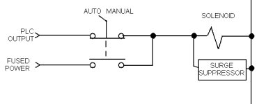
When you want a manual switch as a backup to the PLC, you can add normally closed contacts to the switch to break the PLC control wire to avoid the issues Bob A. speaks of.

The pic shows direct control or the load. If you use interposing relays, you can decide whether to bypass the relay as well, as long as your switch contacts can handle it.

PLC_bypass.jpg
 
Step One

WOW, first I would like to thank all of you for responding. You all have giving me tons to think about, so I thought I would give an update and ask a few more questions. I am sold on using relays, although I do not see the need for auto/manual switch. I can just by-pass the PLC if need be. I’m going to take Bob A’s advise and take baby steps, starting with enclosures. I will be using a type 4 (thanks godfrey) but I’m not sure what size. I want to make this system safe so I want to make sure I get the right “boxes”. The system will be split in to 3 locations, inside the grow environment (~ 5 relays), one located in a utility room (12-15 relays) with a window?, and the PLC enclosure will be in a 3rd room. (office) I will be using the 24 volt DC relay, Allen Bradley is used at my work so, I know it’s reliable but you seem to pay a lot for it. So what’s a 24v 120v/240v relay that is close to the 700-HB Series D Square Base Relays and Sockets? I was looking on grainger.com and they have some clearance relays for cheap, but I don’t want to cheap out and have problems later. Some of the brands on clearance are Dayton and OMRON, any idea if those are decent quality or is this something that it is worth sacking up and paying 10x the cost for the Allen Bradley’s? I’m just not sure if they are “that” much better? What about mini circuit breakers, does cost matter on those or just the ratings? Well, I’ll stop there I have a ton more questions but I am taking baby steps. When I get the size requirements I’ll start ordering. Hope to hear from you all soon. Thanks
 
Top down design

Suggestions:

Draw up a physical layout of the greenhouse which shows the location of the major components. That will help with deciding where to place controls and make it easier to plan wire routing. Putting the PLC in an office area may not end up being the best place for it. Think about how far you wire run$ will end up being versus running one comm cable to the office. On the other hand, putting the PLC enclosure in an environment where it stays hot and damp might reduce the wire runs, but shorten the life of internal components.

A/B makes great PLCs and programming software. If you can afford it, you won't be disappointed with the reliability and ease of programming, not to mention the number of experienced users on this forum.

Choosing relays can be as deep a subject as you want to make it. It's not like you're going to be cycling them thousands of times a day, so less expensive relays may be just fine. If you spend the effort up front for standard plug-in bases, you can get cheap ones at the outset and upgrade as needed if/when they eventually let you down. Putting surge suppression on your inductive loads (solenoids) will make the control contacts last much longer. Just make sure you get relays that exceed the voltage and current ratings of your devices. I have not found any particular brand to be greatly superior to any other, the key is getting the right ratings for your application.

Once you have a physical layout drawing, you can take your list of I/O and draw a schematic of the wiring. Between those two drawings it should be pretty straightforward to figure out conduits and conductors to tie it all together.

We can help with the schematics to make sure you have the right circuit protection where you need it.
 
Last edited:
Hey,

This is my first attempt at building anything like this, so I am going to mock the system up on my work bench. I know it will be a lot more work but I want to have at least a few relays running before installing it in any of the rooms. Once I know what I’m doing I can run the lines to the rooms.The lay out of green house and rooms are close so placement doesn’t really matter.

What is a good program to use for drawing the wiring schematic? I can start on that.
Any thoughts about the size of enclosures I need? Thanks
 
I use Visio which is another piece of MS Office that you can add in. Any drawing program is going to make lines and boxes and they all take a while to learn.

You have a fair number of issues to work through and getting some things on paper is key to getting decent advise. For example, you have a variety of power requirements for you equipment and various locations. These things are going to complicate you system because of the requirement of keeping the right power in the proper locations.

The first thing I try to do is run the complete system from a common power supply at 24 VDC if at all possible. The first breaker or fuse is for the the PLC and it's Inputs, what ever they may be and for the PLC outputs to the Interposing Relays.

Next the power for the loads comes from another breaker to the contacts on the relays and out into the field.

This way you can run the control system with out doing anything in the field for testing, etc. And the field devices can be 120 while the PLC is 24 VDC. If you need 240, then that means that the field devices will need extra breakers, perhaps a single for 120 loads and a double for 240 v loads.

The problem is that all of these various power supplys will be wired to the relays potentially right next to the 24 VDC system for the PLC. This makes it critically important that it gets wired correctly to keep one power system from getting into another by mistake.

I once had a system come into the plant that was made oversees and they had drawings that unfolded into long drawings like a roll of shelf paper. At the left edge, a line was drawn, that was 480 and about half way across, they mistakenly started using it for 120. When they turned on the power, a whole series of 120 V devices got smoked with 480V power.

Another problem that I see is that you may already have power in the field for some of these devices. And now you are going to want to control that power from the central PLC location. If the interposing relay is in the PLC panel, so that the 24 DC is local and "quiet" so to speak, then you are faced with running the remote power all the way to the PLC panel and then back to the load. So do you put the source of all power at the PLC, or do you locate a second relay in the field or do the move the interposing relay into the field and give up trying to keep it in the quiet environment.

I see these issues as the toughest part of the job. And as was mentioned, don't forget to use surge supression on the loads that the PLC outputs see. If you are using 24 VDC then you can put a reversed biased diode (about 100 Reverse Volt Rating) across each relay coil. When the power is turned off, the diode becomes forward biased momentarily and kills most of the kick that would normally get sent back to the solid state switches in the PLC output module.

For AC loads, a resistor in series with a capacitor (RC) supressor is used to do the same thing. They are sold for this purpose and for the diodes, you just buy them from an electronic parts supplier.

For the relays, I recommend the ones that have an indicator lamp in them. That saves a lot of troubleshooting time, when you are not sure about what is going on. It only adds about 10% to the cost, but it saves a lot of time.

Another thing that can save time when you have more that one power supply is to monitor each one in the PLC. You will need to work out a proper interface so that 240 for example can be monitored on a 24 VDC or 120 VAC Input without getting into a problem. The inputs on the PLC often are in groups that are not completely isolated (Outputs to), so extreme caution is required to work through this part of the design.

Your control logic requirement is fairly simple but you are going to wind up with a system that is fairly complicated, power wise. And remember that preventing the un-intended consequences often takes several times longer than getting the normal design elements working. And ultimately, saving time is going to require an effective means to interface with the system so that you are not always trying to figure out what it is doing.

Best Regards,

Bob A.
 
I am sold on using relays, although I do not see the need for auto/manual switch. I can just by-pass the PLC if need be.
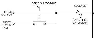
Well, yes, but bypass HOW? Say it is 100 degrees, you come home and your plants are wilted. Something has gone wrong with your PLC. You have to do something quick to save your plants. Now do you take time to remove all the wires from the terminals, or do you install jumpers on all of them, or do you just flip some switches to disconnect the PLC and reconnect your normal power to get your water pumps, chiller, and vent fans running?


My idea for using single pole emergency switches was even simpler than Paul's 2-pole switches (see picture). Use one switch for each device, turn switches off when PLC is being used. The "PLC Output" in your case will actually be a relay output controlled by the PLC. Of course the relay output power and the "Fused Power" should be from the same circuit. You would not need the surge suppressors on the AC portions of your circuits. For 240-volt AC devices, you WILL need a 2-pole switch and also use 2 NO contacts on the relay for that circuit.

Greenhouse Device Dual Control.JPG
 
Last edited:
I was looking on grainger.com and they have some clearance relays for cheap, but I don’t want to cheap out and have problems later. Some of the brands on clearance are Dayton and OMRON, any idea if those are decent quality or is this something that it is worth sacking up and paying 10x the cost for the Allen Bradley’s?
I have used both the Dayton and Omron relays. I found them to be reliable. For your motor circuits, you want relays rated for 10 Amp inductive and "motor starting". That generally means that the contacts are heavier and tougher and can withstand the high short-term currents that develop in the first few seconds while an AC motor goes from 0 to full speed. It appears that the $8.84 cost Grainger Item # 2W927 (OMRON LY1-DC24) will work for 120 volt motors up to 1/2 HP (single pole only). For 240 volt motors, you could use Item # 1A487 at $14.62. For non-motor devices you can use cheaper relays with lower contact current ratings.

Tip: In your PLC program do not allow more than one motor to start at any time. More than one motor can RUN at a time, just limit start-up to one at a time. This will prevent your line voltage from drooping (and thus prevent excessivle high currents through your relays, thus prolonging contact life). There are various standard timing routines that have been in use many years to accomplish this task. I am sure you can find old threads here with such routines, or someone will help you write a new one.
 
Last edited:

Similar Topics

Hello friends I need to monitor and control a greenhouse 8x30 meters, 5 height. The first stage is to install 4 temperature sensors, 4 humidity...
Replies
5
Views
3,224
My boss has come up with the idea of renting machines and charging on a per use / per hour basis, so I'm looking into it - just getting my feet...
Replies
14
Views
3,962
I have an emco lathe I have retrofitted for a new control (mach4) and electronics. I have saved this turret for last because I knew it was going...
Replies
77
Views
29,969
Need help with designing and test a PLC-controlled pneumatic system that conveys manufactured parts and loads them on a packing machine. I am...
Replies
8
Views
2,632
Hi all! I can't seem to figure out what I'm doing wrong. I have wired up my stepper motor, control, and uploaded test programs and nothing...
Replies
2
Views
1,851
Back
Top Bottom