Woodward CSP2-T2 - Modbus

jcrodro

Member
Join Date
May 2010
Location
Quito
Posts
8
Hi everyone!

This is my first post, hope to do it just fine... Let me talk you about my issue:

For 2 days I have been trying to communicate a CSP2-T2 (transformer protection and control system, by Woodward-SEG) through a Modbus RTU network, to a PLC Micrologix 1100. CSP2-T2 as a slave from the network and PLC as the master.

I have read the Tech Manual from Woodward and already done the required connections in the RS-485 port of the CSP2-T2. I tried to access register 10000 of the CSP2-T2, as a Holding Register (as modbus address 410000) from the PLC's MSG instruction, but I have no result...

Also, I have put the BUS-Terminal resistances in the ModBus physical network,,,, no response from CSP2-T2 again...

If somebody has experience in communicating this device, I would appreciatte a lot his/her help. Thank you in advance...

P.D. I'm using the default communication parameters of the CSP2-T2, since I don't have yet the CMP1 module to personalize them, these are:
Baud Rate: 9600 Bd/s (also tried 19200 Bd/s)
Parity: EVEN
Stop Bits: One
Slave ID: 1
 
How do you have the ML1100's serial port set-up? Post your .rss file if you can ( zip it first)
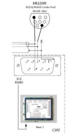
What cable/harware are you using between the two devices? ( wiring diagram if you can)
 
Last edited:
Hi Mickey. Thank you for your response.

The ML1100 has the following Channel configuration:

Channel 0:
---------
Driver: Modbus RTU Master
Baud: 9600
Parity: EVEN

Control Line: No Handshaking (485 Network)

InterChan. Timeout(x1 ms): 0
Pre Transmit Delay (x1 ms): 0


Is that what you meant?


This configuration is due to I have not already configurated the CSP2-T2 ('cause I don't have yet the CMP1 interface unit neither the System Line Software, SL-Soft v2.0 that the CSP2's manual talks about), so I'm using the default values for communications of the CSP2-T2 that the manual indicates...

In hardware: I'm using the configuration that the CSP2's manual talks about, which I recognize as a connection for a Half-Duplex Modbus RTU network,,,

I attach a .rar file that contains the .rss and a .jpg showing my connections...

Thanks again.
 
Did you try reversing the TX and RX wires? 1&8 on the ML1100 side or the other side if its easier.
 
Yes, actually I tried that first, 'cause I was not really sure which one was the A' and B' cable. In every different channel configuration that I test, I always try both ways, 1-8 and 8-1...

Also, I tried the circuit I showed you with a 120 Omhs terminal resistor in the side of the ML100, but I don't think that is the problem..

Greetings.
 
I have just checked the Modbus protocol manual V00_03 for the CSP devices and it appears that default settings are 8, 1, even @19200 baud. I did not find a reference to the default Modbus address though.
SEG devices have their ways about them too. You may find you have to cut back how much data you read at each call.
 
Any indication what the failure is? Failure to communicate or a Modbus exception message (no such register)?

>I tried to access register 10000 of the CSP2-T2, as a Holding Register (as modbus address 410000) from the PLC's MSG instruction, but I have no result...

There's no link to the Woodward Modbus documentation. Does the Woodward support 5 digit addressing (4xxxxx)? Many older devices were only designed for 4 digit addressing (4xxxx).
 
I have just checked the Modbus protocol manual V00_03 for the CSP devices and it appears that default settings are 8, 1, even @19200 baud. I did not find a reference to the default Modbus address though.
SEG devices have their ways about them too. You may find you have to cut back how much data you read at each call.

Hi BobB.


Yes, I was working with that manual too and already tried too with those default parameters:
Parity: even
Stop Bit: 1
Baudrate; 19200
... (Timeout and t call, not important, Am I correct?)
Slave Id: 1

I'm not sure what you mean with "8" (from your text: "...that default settings are 8, 1, even @19200 baud....")

About the default modbus address, the manual just talks about data point lists, which I understand to be the modbus registers to read data, so maybe they are unique, by default...

About length of data, in the configuration window of the MSG instruction, in RSLogix500, I take 16 bits as the length of data to read,that is the usual length in Modbus RTU, am I correct?,, However, I will try to take 8 bits, to see what happens and I'll let you know. Don't really know much about SEG devices, further than the manual indicates.
 
Any indication what the failure is? Failure to communicate or a Modbus exception message (no such register)?

>I tried to access register 10000 of the CSP2-T2, as a Holding Register (as modbus address 410000) from the PLC's MSG instruction, but I have no result...

There's no link to the Woodward Modbus documentation. Does the Woodward support 5 digit addressing (4xxxxx)? Many older devices were only designed for 4 digit addressing (4xxxx).

Hi danw

I'm not sure if I can post a link, but the documentation I have comes from Woodward's web site:

http://search.woodward.com/download_rg/download.php

However you need to register before download any documentation, the two documents I'm using are:

1.CSP2-T Transformer Differential Protection (for CSP2-T2 device info)
2.CSP Modbus RTU- Protocol Desxcription V00_03 (for modbus info)

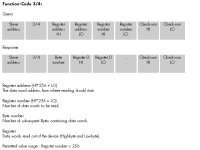
In the 2nd manual, it says that you have "function codes" to carry out modbus commands. For reading a holding registers, the code is 3, and the details are shown in the .jpg attached for you to check.

From that info, I understand that, within the frame, in a query, I have to send the function code number (3, in this case), and, since all the data points have 5 digits (e.g., Nominal frequency fm: 10000), the total number of digits in the addressing is 6: (e.g. 310000, or 410000 -I've tried both-), am I correct?

Also, I have communicated an Woodward EasyGen3200 with the ML100 in the past, in a Modbus RTU network, following the same logics, also with 6 digits, but with CSP2-T2 is not working,,,,

About the error messages, since I don't have access to the CSP2-T2 configuration yet, the thing I can do is to chechk ML1100 documentation to see its mobus error messaging, and try to stablish whether its is a defrinite cause for the communication failure or not. I'll let you know the result.

-----------------

Thank you all for your replies, I`ll let you know as soos as I can the results of my tests.

fc3.JPG
 
Hi again.

I've done some tests on this communication project and have gotten the following results:


- To BobB: In the Setup Screen of the MSG instruction in RSLogix500, there is no posibility of taking 8 bits from the holding register that I want to read in the modbus network, the options are: 16 and 32 bits only; so I went for 16 bits. No result.

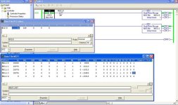
- To danw: The MSG instruction in the ML1100 works with Message Files. Within the Message File Elements, there is a bit sub-element MG11.0/ER that indicates the occurrence of an error in the communication. I'm using the MSG11:0 and, as you can see in the .jpg I attach, the bit is in "0". I though this meant I had no error in the communication, but the truth is that, even when I remove the circuitry for communications, this bit continues in "0", so I think is not fully reliable... There is another sub-element, MG11.0.ERR (taht shows the specific comm error through an error code); however it does not appear in the visualization window of the MSG instruction, as you can see in the .jpg attached, so I was not able to see whether there is a definite problem for the comm or not.... The only thing I saw was that, ocasionally, bit MG11.0/EW (which indicates that MSG is enabled and waiting) and bit MG11.0/ST (which indicates that MSG has been transmitted and ack. by target device) toggled with each other... This could mean that SOME comm is going on,, am I correct?---- But still, no result, and no data change in N12.0 (register where I allegedly put the data from register 1000 of the CSP2-T2 through MSG instruction --- the "6" that appears in the .jpg image is just what I wrote in RSLogix to see if it changed through an execution of MSG)....


Any more ideas?

Thank you in advance

msg.jpg
 
The 8 bits is standard Modbus RTU protocol comms settings not word length.
The word length should be 16 bits.
I do not use the Micrologix so unable to help there.
 
As BobB mentioned, you should be reading 16 bits for a single register read, not 8 bits, as you've discovered. The 8 bits referred to earlier is the number of bits in a byte for Modbus RTU.

> the total number of digits in the addressing is 6: (e.g. 310000, or 410000 -I've tried both-), am I correct?

3xxxxx designates an area of memory in the slave associated with holding registers. In many masters, the leading 3 is typically understood, but not actually used as part of the address. The 04 function code by definition addresses the
3xxxxx area of memory. Modbus manual page 11 shows that 10000 is function code 04, hence 310000

So your register address is probably 10000 (decimal) = 2710 (hex).

The Modbus manual says that register is format F2, defined as "unsigned short" on page 44, which I assume is an unsigned integer, which will be 16 bits in length.

On page 4 it says that the default slave ID address = 1
Are you addressing register 2710 hex at slave 1?

According to page 4, the default baud rate = 19200

I'm not an A-B guy, so most of the screen shots are cryptic.
What does N12:0 0 = 6; 1 = 240 mean ?

Apparently you wrote the 6 into 0; how did 240 get into 1?

Where do you expect to get back as a value from 310000?
50 decimal? Where will the value show up? N12:0 0 ?

I suspect the toggling of the MG11:0 bits is evidence of a one shot attempt to execute the Modbus read transaction.


Hi

Ok, I understood about reading 16 bits.

Now, I still find the whole function code issue very confusing...

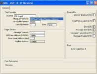
In 1.jpg's that I attach, setup screens of the MSG instruction are shown. The first one, shows what I'm doing. I'll explain the most important setups:

-Channel=0; indicates that I'm using RS-485 to Modbus Network.
-Modbus Command=03; This is the command used in ML1100 to read holding registers from modbus network. As you can see, even when the comand is numbered as "3", is going to address 4xxxxx.
-Data table address=N12:0;Is where I expect to get back the value from modbus address 410000 (in this case).
-Size in elements=1: Not really sure, but guess that it refers to read 1 register of N bits of data only.
-Data=16; The number of bits, N=16, I'm reading.
-MB Data Address=10000; the register in CSP2-T2 that shows the nominal frequency.
-Slave Node Address=1; I'm addressing at slave 1 (the default of CSP2-T2).
-Modbus address=410000; The result of this configuration for the addressing.

As you can see, I'm addressing register register 10000(decimal) (0x2710) at slave 1. I'm also trying with 19200 Bauds/s.

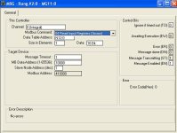
Now that I saw your reasoning about 3xxxxx, I also tried what is shown in 2.jpg; the difference is this setup:

-Modbus Command=04; This is the command that ML1100 defines for Reading input registers; even when the command is numbered "4", is gonig to address 3xxxxx. Provided that this is the correct addressing, I tried this, even when is not, by AB's definition, the command for reading holding registers...

I'm sorry to say that even with 2.jpg's configuration, I have no result...


Finally, answering to the rest of your questions:

-In the previous post. I was implementing a modbus network using both, a CSP2-T2 and an EasyGen-3100-5, by using MSG instructions like the one explained before.

In N12:1, I was expecting to get back 240(decimal), the battery voltage x10 of the EasyGen, through an addressing 410111. Comm, in that case, is successful: When I wrote (force writing) whatever number (i.e. "6") in N12:1, the comm manage to re-write "240" in N12:1, everytime (at the rated speed of modbus). EasyGen is slave 2, and comm works with both 19200, 9600... so it's ok. That's why in the .jpg shown in my previous post (which was a capture screen from on-line comm), N12:1=240.

On the other hand, in N12:0, I was expecting to get back 50(decimal), the nominal frequency of the CSP2-T2, from 310000, or 410000. So, if comm is successful, in the .jpg shown in the previous post, there should be "50" in N12:0. I, on purpose, wrote "6" in N12:0, to see whether it changed or not for "50" in every polling of modbus network (like comm with EasyGen does). It didn't.

Sorry if my screenshots are confusing, and also if my text is too long.....

Thank you for your help.

1.JPG 2.JPG
 
Finally... Success!!!

I've just managed to implement my modbus network: ML1100(Master) - CSP2-T2(Slave1). In the following lines I show a summary of what I've done in the end:


In the CSP2-T2's Modbus RTU-CSP Protocol Description manual, it says that the nominal frequency (the value I wanted to obtain from CSP2) has the address 10000 and that its function code is 4. Therefore, I was trying to read this data register through a MSG instruction of the ML1100 in a modbus network, but it didn't work.

The error was a common trouble that modbus rtu comm has, that some devices do the addressing in a different form, so that address must be increased in order to do the correct addressing.

This was the case of the combination ML1100-CSP2; It was necesary to increase in 1 the direction I was trying to read; so, in the MSG setup screen, the final parameters are now:

...
-Modbus Command=03 Read holding register(4xxxxx); for the function code of fn is 4, so the addressing 4xxxxx is appropriate.
-Data table address=N12:0
...
-Size in elements=1
-Data=16 bits
..
-MB Data Address=10001; Not 10000
...
-Slave Node Address=1
-Modbus address=410001


So, in N12:0, I finally managed to obtain 50 (50Hz, the nominal frequency of the CSP2-T2), a proof that modbus network is running. The rest is history.

For future reference, I attach now the final hardware configuration that I used. That is due to all the changing I did in the wiring.

Thank you very much to everyone who helped me in the solution of this comm problem, showing interest for it.


J.C.R.

HardwareFinal.jpg
 

Similar Topics

Hi Guys Does anyone know how to establish comms between RedLion DSPSX and Woodward 723 governar. The Aim is to Get all the Woodward status to...
Replies
2
Views
1,482
i have steam turbine control valve (moog) and woodward spc i want to caliberate spc according to my valve can anyone help me.
Replies
0
Views
1,879
Dear all, I have a generator / mains setup which is configured using the Woodward EasyGen3000-3500 and Woodward LS5 controllers. When running in...
Replies
3
Views
4,056
Hi All, I am working on a project using Woodward Easygen 3200 and a PLC for remote control. I have figured out how to run the generator remotely...
Replies
0
Views
2,485
i have a problem as there is "reverse KVAR" alarm apears at display what can i do and what the reason of this case?
Replies
4
Views
2,023
Back
Top Bottom