Interposing Relay symbol

Join Date
Apr 2002
Location
Just a bit northeast of nowhere
Posts
1,117
Hi guys!

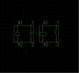
I'm trying to decide on a nice symbol for an interposing relay.
Since it's an in-line device, with local control and a well-understood function, I think the method I generally use is over-kill, and wastes paper space.

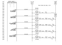
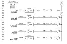
Attached is an image of how I normally do it.

Any suggestions?

TM
 
I use to call to outputs relay in the number of the output in your case R309,
In same way I name my inputs xxx.on switch push button and field device.In that way when you see sensor on field you immediately know where it belong.
 
yep

Arik,

I follow a similiar convention. The numbers in my example reflect an older machine that I have begun to upgrade, and am re-doing the numbering as I go.

My specific question, though, isn't about wiring, but schematics, specifically, how to represent an interposing relay with a single symbol, instead of the two-piece job I use now.

I have a few ideas, but I wanted to see what others would come up with.

Thanks!

TM

PS : Anybody know a good method for removing dried super-glue? Short of sand-blasting? :)
 
Tim, there are a couple of things I don't like on your diagram, some of which are just personal preference.

1) You show the coil and contact in one block, which is confusing. They should be separate items, with the rung of the contact cross referenced on the rung with the coil. This would be in conformance with common practice and the old JIC standards.

2) I ASSUME that BO 03.02 is a source output on the PLC that pulls in the relay. That should be clear. Some guys like to put all outputs on a given I/O card in one block, but I break them up so the logic with the interlocks is obvious

3) I personally don't like using the output to deignate the relay - you can have several devices (like a relay and a pilot light) tripped by the same output. I still use the old JIC format of CR-#### and a separate description of the function

4) I am assuming that circles represent field terminals and octagons internal terminals. That is OK if you have a legend denoting that.

5) I maintain the same wire number on all devices that have the same electrical state. Going through a terminal block shouldn't change the wire number

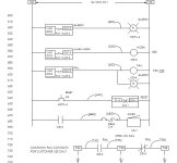
7) I assign the wire numbers based on the rung number. I number rungs in increments of 10, and for example the first wire number on a rung is 710, the second can be 711 or 715 or whatever you want. I don't often have more than three or four wire numbers per rung. This aids troubleshooting, since it is easy to locate the wire on the drawings.

Attached is a diagram I pulled at random - blast away guys!
ladder.jpg
 
Blast away? Phpppt...

Hardly, Tom :) This is very valuable information!

1. I was trying to denote a self-contained device that encapsulates both a coil and a contact. I describe it's specific function in my legend (yep, got one of those). From your comments, I gather you prefer the original approach?

2. That is correct, and on the full page the output block is labelled "active high outputs".

3. My thought is this - I want to make the path as simple as possible to follow. The relay designation is linked to the output designation, since it's only function is to isolate the output.

There is weight to your arguement. I'll have to think about that one.

4. Circles represent terminals. Internal connections are "Tx-xx", external ones are "Sx-xx". The octagons represent line jumps to other portions of the schematic, in this case, the DC bus branch for this particular section of the wiring.

5. Absolutely correct. In this case "Cx-xx" refers to a cable and a particular conductor. I've since abandoned that practice. These days, I just use the I/O number clear through. Simpler.

7. (Hey, what happend to 6?) See item #5.

I look forward to your thoughts.

TM
 
What happened to "6" was I only have five fingers on my left hand, and I always screw up left to right transitions! (OK - 7 should have been 6)
 
Addendums...

Personally, I'm not terribly pleased with the symbol I put up for the relay (that's why I asked, heh heh), but it sure is cleaner and easier to read.

There's no +24 VDC line, since it was only there for the relay contact in the first place, and the symbols and designations for the coil/contact pair are placed in a single in-line unit.

If anybody has any better idea, I'm still very interested in hearing them! Nothing is ever the last word :)

Incidentally, the numbering did not come out of a vacuum. I've seen several schamtics of this nature. The "12" refers to the page number, then the individual line follows.

TM
 
Last edited:
I prefer you way Tim then Tom way.That the way I use to work and I think it more clear.
I put evry 16 I/O on one page.
You can save space if you will change your format little bit.
you dont have to invent something new.
 
+24 -24
Output 1 R1 I I R1
----------------( )--------I I------I I-----------{Load}
I I
I I

]

 
Last edited:

Similar Topics

Why there is a requirement to connect interposing relay when we are using relay output type PLC?
Replies
14
Views
4,891
DEAR ALL, COULD ANYBODY help us for the following issue... how to wire the INTERPOSING RELAY CONNECTION TO PLC...
Replies
12
Views
3,202
In a project,I am using an Output Card where I have been advised to use 24VDC interposing relays to give output signals to field elements. I have...
Replies
9
Views
4,379
Hi Team I need technical advice of using an interposing relay;is possible to connect two PLC through an interposing relay which will be located...
Replies
16
Views
4,056
I read the following post: http://www.plctalk.net/qanda/showthread.php?t=49630&highlight=interposing Kid mentioned the 700HL interposing relay...
Replies
10
Views
5,230
Back
Top Bottom