Newbie with Q64AD Mitsi Q

robwright

Member
Join Date
Oct 2010
Location
Derby
Posts
5
Hi all, I am a maintenance engineer at automotive factory in midlands, UK. Am currently installing a SCADA system using Mitsubishi Q06 PLC, and want to monitor water temperature leaving welding robots. On testing rig (using Q02HCPU) have managed to get the Q64AD to read correctly, but when introduced into proper PLC rack and all addressing setup I read arbitrary values in my registers of 60, 20, 20, 10 etc. Have set up my switches accordingly and like i say it seems ok on test rig I know this is all a bit vague news, but its my first crack at A-D conversion.

Slot 0 - QJ61BT11N - CC-LINK
Slot 1 - QY81P - O/P
Slot 2 - QJ71E71-100 - ETHERNET
Slot 3 - Unmounted
Slot 4 - Q64AD

Does anyone know of any conflicts that this setup could cause etc?

My kindest regards and thanks in advance,
Rob Wright.
 
I had a similiar issue on a mitsubishi project with the same card you are talking about, and found that the servo motor was creating a lot of noise. Rerouting the wiring away from the servo motor wires, grounding the shield correctly, and cleaning up the a/c power into the 24vdc power supply cleaned it right up.
 
Many thanks for your help guys, sorry it took so long to get back but this is really a side project. I have eventually managed to get the card reading quite happily, but I dont really understand why. I have had to use the card in slot 0. Nowhere else would do but it seems fine there.

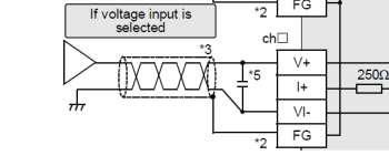
The next issue i have is i am trying to read a water temperature output from an IFM Efector 300 SM7000 flow/temperature monitor. I believe i have setup all my switches and scaling correctly but i am struggling with reading the unit. The Q64AD calls for V+ and V- to be wired up, however I only have a single wire o/p for voltage from this unit, and wiring the single wire causes most erratic readings. Again I havent ruled out noise (the company cannot afford screened cable - so if that is the case the project goes on the back burner) but i get similar results wiring up just one wire of a 3V battery.

Again, Im sorry its so wordy but i struggle to condense this stuff - any ideas?

Many thanks in advance, and thanks for reading all this pap!
 
First of all I assume 0-10 v output from the sensor
assume that the sensor has a 24v supply to power it and this unit is 3 wire i.e +24v 0v and 0-10v output then the - of the card goes to the -v of the sensor the +v of the card goes to the 0-10v output of the sensor.
you really need to use screened cable & earth only one end, also in many circumstances it is better to ground the 0v of the 24v psu supplying the sensor.
if the unit is a 2 wire 4-20ma then to make it active connect 24v to the +ve of the sensor the -ve of the sensor goes to the I+ of the card & the I-v goes to the 24v psu 0v.
 
Parky, Thanks for your reply, The sensor is a one-wire o/p set to 0-10V, so I have tried using the V- of the sensor and also grounding the 0V to no avail. I can only imagine that noise and drop distance is the driving factor here. The one thing that troubles me still is that the readings given by the unit in the PLC register match up with what happens when only the V+ of a 3.6V battery is wired in. When both V+ and V- of the battery are wired up everything seems ok. Having used both 0V and ground for the V- I am strugglingt o come up with where to go from here.

Again, many thanks for your reply,

Rob
 
Oops got the wrong thread, I was looking at the FX3u but it is simular & you will find the manual on the website
 
OK, My apologies the random value issue was seemingly me down to setting my switches the wrong way round. 0005 for 0-10V in CH1 when it should be 5000. I now have a value of 3480-3500 @ 8.5V which seems in common with what the Q-series programming manual states is expected (4000 @ 10V). The question I have now is what to do with this data? I have easily divided it by an arbitrary value to get the desired result, but feel like there is probably a function that can be used to read this data as °C. Does anyone know of this?

Again, my thanks for your help and patience with me on this one - cant thank you enough guys!

Rob.
 
The best way is to write a function that scales the 0-4000 to whatever you require i.e. if 0-100.0 then convert to float the raw data, then multiply the raw by 40.0 this will give you scaled data i.e. raw = 2000.0/40.0 = 50.0 or 1937/40.0 = 48.425
the 40 is derived from max raw/scale (4000/100)
You could build in an offset as well as span so you can calibrate it.
 
Thanks for all your help on this guys, project is now closed. Sadly, due to Mitsi's inability to deal with remainders have had to read the value rounded up to the nearest whole integer.

But all good now, Cheers all.
 
if you know how to use all maths functions on mitsi Q there should be no problem, we have over a hundred systems number crunching & there is no problem.
 

Similar Topics

Hello all, I'm a new member here. I've joined as I want to learn about PLC programming. I've got a few questions to begin with. To get me...
Replies
37
Views
4,546
Howdy folks. Been doing PLC programming for like 15 years now in LD and ST, but I'm trying to learn SFC now and have a kind of dumb question... I...
Replies
4
Views
1,384
Hello. New to Unity and had a couple quick questions. Can a Modicon M340 output to a small multiline LCD screen and not a full HMI?
Replies
4
Views
961
Hi. I'm learning AOI programming in RSLogix 5000. I created an AOI with several input and output parameters but when I choose the AOI in the main...
Replies
17
Views
3,200
Good morning, I've had an inverter fail with firmware revision 5.002, the only spare is Rev 7.001, when updating the project with the new...
Replies
2
Views
1,259
Back
Top Bottom