PWM to 4-20mA Output

Frelecing

Member
Join Date
Oct 2010
Location
Uruguay
Posts
73
Hi everyone:

I'm using a Crouzet Millenium 3 (XD10 with SSR outputs) to control the speed of a motor. The motor has an analog input of 4-20mA. The Millenium has an "analog output" that can only give a PWM signal.

Is there any way to convert this PWM to a current signal? Are there any transducers, or do I have to build the circuit to achieve this? If you can guide me on how to do this I'd be more than grateful.

Thanks!
 
Thanks for the info, but isn't there any homemade design I can make on my own? Because I can't find that device in my country...
Thanks anyway.
 
Is there any way that the drive can accept an analogue 0-10VDC signal instead of the 4-20mA?
If yes then a simple voltage divider and capacitor circuit may work just fine.
 
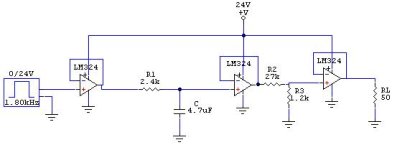
I think I'll use this circuit I'm attaching. I don't know if the 3 voltage buffers are necesary, but as the LM324 has 4 Op-Amps, and they don't affect the result in a negative way, why not?

Unless you tell me there's something wrong, I'll give that a try.

The 50ohm load at the end is the input impedance, and with that I get the 0-20mA I need, don't I?

Thanks for your help!

LP.JPG
 
That circuit will work, but the final amplifier has it's input hanging out in the real world. In my experience this will not last long, you need some isolation between the inputs and the outside world. Resistors work nicely for this, as well as a decoupling capacitor or two.
 
the final amplifier has it's input hanging out in the real world. In my experience this will not last long, you need some isolation between the inputs and the outside world. Resistors work nicely for this, as well as a decoupling capacitor or two.

Thanks for your advice. I know this topic has gone far away from PLCs discussion, so sorry about that...

But what exactly do you mean by "the input is hanging out"? And by saying that it won't last long, I assume you're refering to the Filter alone, or do you think it can damage the Crouzet or something worse?

I have so little experience with electronics, and doubt so much on my own judgement that I'm really afraid of damaging expensive equipment by simple mistakes like this!
 
It all depends on your environment. The circuit you presented looks like it came out of a textbook. Typically an industrial circuit would have some protections built in to guard against static discharge, dead shorts on the output, dirty power supplies, etc.. Op-amp inputs are not well protected by themselves and the outputs are not a lot better. If this is not a critical application, use a socket for the IC and go for it. At a minimum, use a 0.1uF capacitor connected across the power supply pins of the IC, and for the unused amplifier tie the output back to the (-) input and the (+) input to ground. If left floating these can sometimes do weird things. If you want to know more about op-amp design, the OP-Amp Cookbook is a good place to begin. Good Luck!
 

Similar Topics

Good morning! I'm trying to find a DIN rail-mountable 4-0channel PWM amplifier that is capable of accepting a 5VDC PWM with a maximum frequency...
Replies
2
Views
108
I have a project to control the speed of motor DC using PWM Output on PLC and when im on working i have a several trouble and of of them is the...
Replies
6
Views
212
Hi All, I came up with this for ramping the PWM pin on the micro 820. I'm new to ladder logic so I am not sure if this will even work? Once...
Replies
6
Views
349
Hi, I am trying to have my PLC start a heating fan in a linear manner. A certain percentage at a certain received setpoint. To do this, I use a...
Replies
8
Views
1,583
Hi guys, i have never had to do a PWM Output or input before i have a Device that to dimm the lamp output from the ballast, the ballast has a 24V...
Replies
6
Views
1,044
Back
Top Bottom