cycle time of a revolving wheel

tny

Member
Join Date
Jun 2005
Location
usa
Posts
105
hi,
what is the easiest way for measuring the cycle time of a revolving wheel with a single sensor and an s7 300 plc ?

i need the time values between sensor pulses. this time values are about 0,5 - 1,5 seconds.

the code should not be affected from PLC programe cycle.

thanks
 
Last edited:
set urself up a one second clock memory pulse, use the rising edge to pulse a counter which counts to 6. Count the pulses from the sensor in this time and multiply by 10 to get pulses per minute or RPM.

Sounds like a homework puzzle so i will leave it to you to figure out the logic for it.

LH
 
set urself up a one second clock memory pulse, use the rising edge to pulse a counter which counts to 6. Count the pulses from the sensor in this time and multiply by 10 to get pulses per minute or RPM.

Sounds like a homework puzzle so i will leave it to you to figure out the logic for it.

LH

clock memory times are too long for this app.
i need time values of max 10ms resolution.
 
Why do you think we have a crystal ball to get the basic values?
Much simpler to tell us up front.

Do I correctly infer you have no idea of what the RPM is? It is really simple 8th grade math to figure out the time for one revolution.

If you have no idea of what the two values are it seems to me you have no idea of what your process is and you are nowhere near ready to even tinker with a PLC.

Dan Bentler

OUCH!! :eek:

Don't forget we were ALL in 8th grade once [maybe twice in "TNY"'s case].

LOL
 
Just wait, tny asked a valid question. He stated that he needed to measure short time periods rather accurately and implied that the scan time variance would not be fine enough resolution. Maybe guidance in the high speed capabilities (if any) of the system he mentions would be in order. A long term timing of multiple occurances seems to be ruled out by his question. Homework or not, it appears he has give some thought to the matter.

By the way, his previous posts seem to indicate other than 'homework'.
 
hi,
what is the easiest way for measuring the cycle time of a revolving wheel with a single sensor and an s7 300 plc ?

i need the time values between sensor pulses. this time values are about 0,5 - 1,5 seconds.

the code should not be affected from PLC programe cycle.

thanks

What is the minimum time the sensor pulses will be on for ?

Which CPU will you be using ?

Do you have to worry about the case where the wheel is stopped and is just on the edge of the sensor resulting in counts due to vibration ?

Will you consider adding a counter card ?
 
Why do you think we have a crystal ball to get the basic values?
Much simpler to tell us up front.

Do I correctly infer you have no idea of what the RPM is? It is really simple 8th grade math to figure out the time for one revolution.

If you have no idea of what the two values are it seems to me you have no idea of what your process is and you are nowhere near ready to even tinker with a PLC.

Dan Bentler

the time values between the pulses are necessary to calculate the diameter of the wheel angry guy. if you do not have any technical comment please do not pollute this thread.
and may be you should hang out with friends more to learn how to speak like other people.


Just wait, tny asked a valid question. He stated that he needed to measure short time periods rather accurately and implied that the scan time variance would not be fine enough resolution. Maybe guidance in the high speed capabilities (if any) of the system he mentions would be in order. A long term timing of multiple occurances seems to be ruled out by his question. Homework or not, it appears he has give some thought to the matter.

By the way, his previous posts seem to indicate other than 'homework'.

it's nice to see right-minded people here :)


What is the minimum time the sensor pulses will be on for ?

Which CPU will you be using ?

Do you have to worry about the case where the wheel is stopped and is just on the edge of the sensor resulting in counts due to vibration ?

Will you consider adding a counter card ?

the pulses are 50 msec long. (on time)
the cpu is cpu314.
the stopping point is not important. i think there will not be any vibration problem but anyway i used a positive edge trigger after the input on my program.
and sure if necessary i may add a counter card.

the siemens 314 cpu and has counter inputs but they are already used to get data from encoders.

today i tried a way to calculate the time values between pulses by using normal timers, with no any hw interrupt, high speed counter etc. i simulated the pulses (50 msec pulse on - 250 to 1450 msec off) and i saw that the code works on an empty plc with 1 msec cycle times.

but with the cycle times of 30-40 msec with all codes, the code calculates the times with 20-30 msec excess.

step7 is not installed on this pc so i can not copy the code here, i'm sorry. i will add tomorrow.

regards
 
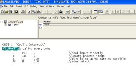
Set your cyclic interrupt time to 10ms in the h/w config.

Perform your processing in OB35 based on the fact that OB35 will run every 10ms.

To ensure the process image is up to date you have to load the peripheral byte of the input you are using and copy it to the process image e.g.

pib.JPG
 
thanks, this will be very useful for me:)

To ensure the process image is up to date you have to load the peripheral byte of the input you are using and copy it to the process image e.g.

does it mean, when the inputs are read as pib, they are used like immediate inputs on s7-200 plcs?

and, i knew that the ob35 is 100msec interrupt, how can i set the ob 35 to 10msec?

regards.
 
H/W config - double click on CPU then select Cyclic interrupts

Yes - L PIB reads from the peripheral, copying to IB make the inputs avaiable using A Ix.y
 
i did a similar project 6 months ago.
i used a timer to produce puls every 10ms and then i used a counter to count how many pulses there were when the input was low and then restarted the counter when the input was high
 

Similar Topics

Hello PLC friends. I've been going through a saga of diagnosing and fixing an old PLC setup that I inherited. I am learning as I go. Initial...
Replies
14
Views
329
Hi everyone. I have an issue with an Allen Bradley PLC model 1769-L30ER. This PLC had a previous program with a different IP address but when I...
Replies
4
Views
509
My Panelview plus 700 HMI stopped working and I replaced it with a new one. Moved the sd card from the previously installed panel to this one and...
Replies
16
Views
978
Hi everyone, I recently put in a 1769-AENTR, and where it is installed has had a couple power outages. Every time when the PLC comes back online...
Replies
3
Views
682
Hello Friends, I am looking for a way to take my PID Output( it is the result of my PI Algorithm in Real format) and generate a PWM Signal in...
Replies
16
Views
2,471
Back
Top Bottom