clickerguy

CLICKERGUY

Member
Join Date
Nov 2010
Location
Florida
Posts
42
Really basic question..... using a (AUTOMATION DIRECT) CLICK PLC ...... My first instruction set wants to be "Do nothing IF the RUN/STOP switch is in RUN condition (logic 1) when the power is applied to the machine. After resetting the RUN/STOP switch to off (logic 0), wait until the RUN/STOP switch is pressed to start the machine operation. How do I accomplish this in the CLICK ladder?
 
Set a bit if the Run switch is on during the first scan.
SC2 is the First Scan bit. C1 is used to disable machine operation if it's Set. It is your Master Enable.
Run And SC2 = Set C1
Not Run = Reset C1
 
Still NOT understanding....

Maybe I wasn't clear enough on my first question. The RUN/STOP switch I'm referring to is NOT the one on the front face of the CLICK PLC. It is a function switch on the machine I'm building. In other words, the coding that I'm stumped over could also be called an "anti tie-down" condition. I've coded such functions using microcontrollers many times in the past, but they were written in Assembler, BASIC and/or "C", and I've never had a problem w/ its operation. Ladder Logic programming is new to me, and somewhat confusing to boot.

I looked at the instruction set for the CLICK PLC (www.AUTOMATIONDIRECT.com), and I don't see any reference to a "Master Enable". This is their introductory PLC product, a "baby" PLC, if you will. The list of instructions for this device is rather short.
The Contacts list includes: Normally Open, Normally Closed, Edge & Compare.
The Coil Instructions list includes: Out Coil, Set Coil, Reset Coil
The Timer/Counter list includes: Timer (On-dly, Off-dly);
Counter (up, Down, Up/Down)
The Advanced Instructions list includes: Math (decimal), Math (Hex), Drum (Time-based), Drum (Event-based), Shift Register.

And, finally, the Program Control Instructions list includes: Call instruction, Return instruction, For instruction, Next instruction, & End (conditional & unconditional).
 
Place the majority of your code in a subroutine. If SC2 (First Scan) is true and your "Run" is true then set a bit. If the "Run' is false resety the bit. Only jump to the subroutine if "Run" is true and the bit is false.
 
Bernie: What if there are outputs in the subroutine that are already set following a power cycle? Then, no jump occurs, so would those outputs remain on?

I think we might recommend avoiding conditional subroutines in the beginning with a new PLC guy.

ClickerGuy: The main thing to understand about ladder logic coming from most any other language is that the main program is an infinite loop. All the rungs execute several (hundred) times per second, otherwise the PLC will fault (watchdog). So, there is no stopping and waiting like you would with other languages.

The SC2 first scan bit is only true during the first scan of the program when the PLC is powered up (or placed in run mode). So, you can use that bit in series with your Start switch input to determine if the start switch was already on when the program started.

So I would use the NOT condition of the SC2 bit to break the seal in logic for a main run rung.

As for anti-tie down, you should be able to use a oneshot, or rising transition bit from your input switch to trigger a cycle start. I am not familiar with the Click, so my terminology may not match.
 
Place the majority of your code in a subroutine. If SC2 (First Scan) is true and your "Run" is true then set a bit. If the "Run' is false resety the bit. Only jump to the subroutine if "Run" is true and the bit is false.
Thanx, Bernie. I'm a newbie to Ladder programming, and it's very alien to me. The textbooks that I've read all say how easy it is, but it's not so easy when you've been programming top-down code for the better part of almost 50 years. I tried the original suggestion, and I still can't get it to respond properly. I did not know about SYSTEM CONTROL bits, or even CONTROL bits. Even though I bought this CLICK new recently, I don't have a software manual. That was extra $$, so I've resorted to studying Phil's book and perusing the HELP section within the editor.
 
Bernie: What if there are outputs in the subroutine that are already set following a power cycle? Then, no jump occurs, so would those outputs remain on?

I think we might recommend avoiding conditional subroutines in the beginning with a new PLC guy.

ClickerGuy: The main thing to understand about ladder logic coming from most any other language is that the main program is an infinite loop. All the rungs execute several (hundred) times per second, otherwise the PLC will fault (watchdog). So, there is no stopping and waiting like you would with other languages.

The SC2 first scan bit is only true during the first scan of the program when the PLC is powered up (or placed in run mode). So, you can use that bit in series with your Start switch input to determine if the start switch was already on when the program started.

So I would use the NOT condition of the SC2 bit to break the seal in logic for a main run rung.

As for anti-tie down, you should be able to use a oneshot, or rising transition bit from your input switch to trigger a cycle start. I am not familiar with the Click, so my terminology may not match.
Thanx.... I've TRIED EVERY combination of N.O, N.C. contacts for the SC2 & the X001 (RUN/STOP) switch. At present, I'm working on coding, so there's NO real machine involved. I have a slide switch wired to the X001 input, and some inductive sensors to some of the later inputs. The basic 6 outputs (PNP), I have a string of green LEDs. Once I get the logic down pat, then know I can transfer that to actual pneumatic actuators, and other load devices.
 
As OkiePC mentioned there may be code (initialization type) you wish to run on first pass. Especially those dealing with conditions which were on at power down and whose state have been carried over. Unlike your other code the PLC startup is not a 'tabula rasa'. These type controllers many times attempt to pick up where they left off.
 
I had downloaded the software and looked at it once, so I thought I would give it a shot. It's actually pretty easy to figure out (coming from an extensive Allen Bradley background).

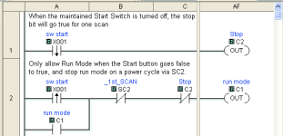
See if this picture helps (I have no way to test it):

If it works, then use a N.O. contact from C1 to condition the rest of your logic.

clicker_001.png
 
Last edited:
Thanx, OkiePC! I really appreciate your input. I am in the process of trying these w/ the wired setup I have on the bench. And, I ordered a copy of the CLICK software manual, so now I will have more reading material. This whole process is "strange" thinking to me, since I have so many years of linear programming experience. I also am concerned about the condition that can exist in which the PLC will scan the inputs on its first scan after power up, and what it does to reset the machine to a "home" position. Even that has NOT been an issue for me in previous projects, since the program ALWAYS started at the beginning. This is why I'm taking "baby steps" to solve individual operations of this machine.
 
If I understand correctly, you're using a maintained switch for run/stop, so try this version instead:
Two observations:

1) Yess! The RUN /STOP switch is a maintained contact sw. In my present test setup, I'm using a simple slide switch because that's what I had in my scrap box w/ wire leads already soldered onto it.

2) In my case, "Every stumble does NOT strengthen the knees"...... it brings me that much closer to the orthopaedic surgeon for replacements. (Ha! Ha!)
 
Well let us know how it goes, and be sure to come back here for any further questions.

As for controlling the sequence of operations, I would recommend that you get a list of steps or a flow chart on paper and put a copy on here so the Direclogic gurus can help you go from that plan to a program.

It might be wise to always start from step 1 or a home position, or it might be a disaster, depending on the machine you're controlling, so put lots of thought into when/why to reset the sequence, and make sure you arrange to have the right sensors in the right spots to keep things in step.
 
If I understand correctly, you're using a maintained switch for run/stop, so try this version instead:
OkiePC:

I tested the coding you proposed here, and it works GREAT! As I mentioned previously, I have connected 4 inductive sensors to inputs X005 thru X008. Each of these is connected to outputs Y003 thru Y006. When I powered up the CLICK w/ (my) RUN/STOP slide switch in the RUN position, NONE of the ouptuts were activatable when I put a screwdriver in front of each sensor. Then I pushed the slide switch to the OFF position, and tried each sensor again. Still no activity on the output LEDs. Finally, I set the RUN/STOP slide switch to the ON position, and now when I put the screwdriver in front of each sensor, the associated LED lights as long as the screwdriver is present.

Even though I've used the "flag concept" in countless program projects in the past, I didn't see the connection in this LADDER programming. I think my mind is getting to "calcified" to accept a whole new way of thinking about programming. I'm not sure at my age that it's worth the effort. It may be a lot more efficient to return to what I know best, ones & zeros!!!

In any event, I THANK YOU VERY MUCH for all your assistance.
 
Back
Top Bottom