a little confused

jtashaffer

Member
Join Date
Aug 2009
Location
KY
Posts
415
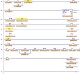
I am working on a new program. It is for a AB micrologix 1200. The problem i am haveing is that the pressure switch, vibration switch, and limit have a light on the panel to say they are operating normal. If the pressure switch,vibe, or limit kick out and shuts the machine down it will turn that light off. Once the light is off and u reset the limit switch, I need the light on the panel to stay off untill I hit a reset button, which turn the light back on. If any one can help, the program is attached.
Ladder.jpg
 
Shouldn't the bits that turn on the lights be XIO not XIC? The way it is now would only energize the lamp output if the switch is tripped, and it would turn off when you hit the reset button.
 
Does anyone else have any ideas

I will change the bits to nc. But there must be something I am missing.
 
First of all, ignoring your lights and reset, is the actual Centerfuge (actually Centrifuge but we won't worry about spelling) operating circuit working? Does it kick out if an error condition occurs.

You appear to latch and hold when the tripping conditions are normal. Don't you want to latch when the conditions are bad?

Label you inputs with what the condition is when it is TRUE. For example, if the vibration switch is true when the vibration is excessive then name it VIBRATION EXCESSIVE.
 
Last edited:
It does kick out the centrifuge if a error condition occurs. The problem I am having if the limit switch kicks out and the limit light goes off, letting me know the limit kicks out. I just don't want to be able to reset the limit switch and the light comes back on. I want to hit a reset button before the light will come back on.
 
You are latching the wrong condition. To help you see this change the names of the inputs as I suggested. Secondly change the name of the latching bit to something like Vibration_Excessive_Latch. Then it should be clearer to you what you are doing.

Then, turn on the latch if the tested condition is BAD. Then your reset, as you have it, will work. In the centrifuge start rung test for a NC of the latch bit. That way you won't be able to re-start after a bad condition until the condition is corrected and the 'reset' has been pressed.
 
you are right, i am latching the wrong condition. But i am not sure on what to do. I labeled the bits the way u explained.
 
If you have modified the names of the input and the latching bits and modified the latching rungs to latch the BAD condition then your rung to turn on the centrifuge should be easy to set up, just read the names. You should have a NC of each of the latching bits since you don't want to start or continue if one of the latching bits is on. Make sure you OK lights come from a NC of the latching bits also.
 
I attached the file with the chages. I took out the latches and the reset rung. The way it is now if the vibration switch trips it will shut the centrifuge down. But you can just reset it and you can start the centrifuge. What do i need to do to add a reset and the latch and unlatch bits?

Ladder.jpg
 
OK add a rung under each of the B3 bits. Example: under rung 2 if you do not have B3:0/0 latch an alarm bit. Lets say B3:0/5. Place the XIO of that bit in series in rung 3. So if you do not have B3:0/0 latch B3:0/5.The XIO of B3:0/5 with prevent the light from comming on if you have an alarm. How you want to reset it depends on you. Maybe a reset button on the panel? In that case use the input from the reset button and unlatch B3:0/5 if conditions are right.
Do the same thing under the remaining B3 bit rungs. Just use B3:0/6 and B3:0/7. You could just branch around B3:0/5 in the reset rung.
If this confuses you let me know......LOL
 
I added the wrong with the alarm bit. In the way u describe, i think could you show me a written code example?
 
Please attach the RSS file from your current form of the project, but first, if you haven't already done it, please label the inputs (the TWO oil pressure inputs, vibration and limit switch inputs) by what the state is when the input point is ON. Then we can work with it.
 

Similar Topics

Hi guys, this should be extremely easy for someone to answer but I am practicing writing my first Rslogix 5000 program. I am very familiar with...
Replies
2
Views
1,689
Hi, Need a little bit guiding using SISTEMA software. As I understand a subsystem consist of components and are the same category. I'm confused...
Replies
11
Views
2,617
Good morning everyone, I've got 2 servo driven axes that each use a Heidenhain glass slide to the motion controller for position and velocity...
Replies
4
Views
1,400
RSLogix 500, what is the little image next to the ladder in the project tree? it looks like a little blue bug with a red dot on its back. just...
Replies
5
Views
2,038
Hi everyone, trying to get data out of a digital encoder that is little endian into my Siemens S7-1200 controller that is big endian...it's an...
Replies
7
Views
3,337
Back
Top Bottom