linear speed calculation

mutabi

Member
Join Date
May 2009
Location
OH
Posts
90
Hey guys,
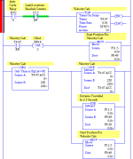
I am trying to calculate the linear speed of a machine. The machine runs off of an encoder so I am using a looping timer to grab snapshots of the encoder every few seconds. Then I calculate the speed from distance/time.
Is there any better way of doing this? The resulting speed varies somewhat. I am not sure if it is a flaw in the programming, or if the process is actually varying. I have no other way of measuring the linear speed accurately.

Can someone take a look at the attached program and maybe offer suggestions?
John
 
Not enough information.
SIMPLISTIC
feet per minute = shaft RPM x circumferance
total pulses = shaft RPM x pulses per Revolution

What is machine - what does it do.
When you get this information what are you going to do with it?

Have you taken RPM measurements of machine to see what the typical variation in RPM is between no load and full load? Have you calculated linear speed?

Dan Bentler
 
Your logic is dependent on the timer .acc value being equal to two specific values in order to store what I assume is a scaled (floating point) version of the machine position. If you PLC scan time exceeds 10ms, you can expect to miss one of those EQU statements.

I would change the logic so that you still use the self repeating timer, but set it up so that it never gets done, and when it reaches the value you are looking for (2.50 seconds), simply subtract that from the .acc to reset the time, but retain the internal timestamp of the timer and not lose any accumulated milliseconds for the next go-round.

Then, I would try (if possible) to store the actual encoder counts, not the scaled value, since that will enhance the accuracy.

Also, 2.5 seconds might be too long. Maybe it will work better with 1/2 second intervals? Perhaps the value you are reading or displaying will be better with some averaging of the last 5 readings taken at 1/2 second intervals? Then you are still updating every 2.5 seconds, but may smooth out the bumps.

It would also help to know the facts that Dan is looking for, especially how many pulses per 2.5 second period is typical.

Also, if this value is coming from a HSCE card, it might be possible to configure the card to tell you the rate, and then simply scale it.

EDIT: Example of how to make the timer more precise:

mutabi_000.png
 
Last edited:
Thanks for the replies guys.

The machine is a finning machine. Basically a screw type operation. As it is finning a tube, the tube pushes against a rabbit which is attached to an encoder. i.e. as the tube fins, the rabbit moves and so the encoder counts. I simply need to know how fast that tube is moving the rabbit.

For every inch of tube that moves past a fixed point, the encoder will count approx 130 counts (depending on the machine). I found that out by finning a big long tube, seeing how many counts it took, measuring the tube and dividing.

Typically the tube will move at approx 1.5 inches per second. So approx 500 counts every 2.5 seconds. The encoder is tied to a 1771-IJ/IK encoder card which we use to tell the position of the rabbit/tube. The F11:5 number is not a scaled number. It is the number of pulses received from the encoder. i.e. the position of the rabbit.

I tried changing the timer down to 1.5 seconds but that seemed to make the speed change even more. I will go even lower and see what happens.

I am also in the process of trying to determine the RPM of the main motor. It is on a VFD and according to the VFD it is not changing under load. I do not really believe that. So I am investigating ways to reliably measure the arbor speed under load. It is not an easy thing to do while the machine is running.
 
OK so you have two independent (not mechanically coupled) actions I ASSUME.
Tube is rotated using one drive
AND fins are put on in a "screw" configuration driven with another drive.

GOAL to derive the pitch of the fins on a tube.

I think if my assumption is correct you have to measure RPM of tube (endoder) AND the linear position of rabbit. Cranking these thru some math you should get pitch.

If they were mechanically coupled then the mechanical drive would automatically control pitch. TO change pitch change the pitch of the lead screw.

Dan Bentler
 
You must create a time base 2.5 seconds (1.25 second on / 1.25 second off).
From every positive front of time base you must run this code:

x_current_position = counter_encoder / 132 ; //Conversion couter in inch
Speed = (x_current_position - x_old_position)/2.5 ; // Time base is 2.5s
x_old_position = x_current_position;


For high speed is recomanded a time base lower.
 
Last edited:

Similar Topics

i have a rotary encoder that sets on a roll and material travels over the roll. i need to calculate linear speed as my material travels over my...
Replies
1
Views
1,265
I've just gone through the exercise of converting a dwell time on a conveyor to an effective motor speed to achieve that dwell time. During this...
Replies
3
Views
1,681
Hi Everyone, Working on my first job that will have some motion functions. The process involves pipe running on a conveyor system. The conveyor...
Replies
10
Views
2,578
Hello Everyone! I have a motion application I need some help with. Here is a sketch: I need to be able to control the speed of the linear...
Replies
16
Views
5,340
Hi, We want to buy a linear actuator 24VDC. We want to control this with a circuit board fro electromen...
Replies
8
Views
2,287
Back
Top Bottom