Ultra 3000i w/DeviceNet Par.358

Adam303

Lifetime Supporting Member
Join Date
Aug 2009
Location
Chicago
Posts
587
Hi to all. I have a 2090-DSD-005X-DN Ultra 3000i servo drive that I have been experiencing with. I have set up communications with the drive via Device Net and a 1756-DNB DeviceNet Scanner(located in slot 1). I'm using Instance Id 9 output assy. and Instance Id 12 Inputs assy.
*In UltraWare I'm using Indexing as my operation Mode.
The issue I'm dealing with is I want to be able to write to parameter 358 Index 0 Distance/Position. I have read the manual Publication-RM004B-EN-E but I don't know how to set this up in my program Logix 5000. I have set up a similar program to the one I found from Ab's site but its for a CompacLogix Processor I'm using Logix 5550. Here is a snap shot of the logic.
Can anyone please help me in achieving this.
Thank You.
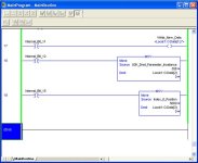
Logix5000.jpg
 
Do you want to use the Assembly 9 mechanism where you load the Output image with the Parameter Number and the Parameter Value then toggle the "Write Value" bit ?

Or do you just want to send the value using a MSG instruction ?

There should be very little difference between CompactLogix and ControlLogix for this application; both the 1769-SDN and 1756-DNB have a 32-bit I/O table. I would try to build (or have the DNet Tag Generator do it) a UDT that represents Assembly 9.
 
I took a closer look at your logic and I think you've got an issue with the data offset.

The "Write Data" bit is correct, but you also need to load the Parameter Number (starts at byte 05) and the Parameter Value (starts at Byte 07).

If the assembly were 1 byte shorter, these would line up better. But they don't so we have to work around it in logic.

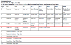
Keep the definition of Assembly 9 handy; the diagram on page 2-18 of the 2098-RM004 manual is what I use.

2098_pg2_18.png
 
Do you want to use the Assembly 9 mechanism where you load the Output image with the Parameter Number and the Parameter Value then toggle the "Write Value" bit ?
Or do you just want to send the value using a MSG instruction ?

For the time being I want to load the Output image with the Parameter Number and the Parameter Value then toggle the "Write Value" bit
When I complete this I want to try using the MSG instruction.

With the setup that I have I don't understand how to offset data for the parameter load. I understand that the MOV instruction (rung18) moves 358 to the entire 32 bit I/O table instead it should only use byte 5 and 6 for the parameter number.
Now that I took a hard look at the Definition table that you posted it seems that I'm moving the Parameter to the wrong I/O table instead of Local:1:O.Data[2]
I should be moving the parameter number to Local:1:O.Data[1] and the value to Local:1:O.Data[2](is this what you wore referring to as you says I have an issue with data offset?) I hope I'm not creating more confusion with what I think, but
again I'm going of a some sample logic that I have downloaded from AB's web site.
 
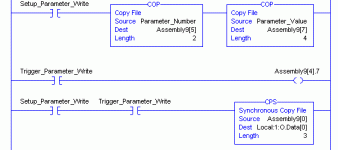
Try using a SINT[11] array to hold all the bytes you're going to move into the output table.

Use an INT tag for the parameter number, and a DINT tag for the parameter value.

Use the Copy Synchronous (CPS) to move the data all together from the SINT[11] array to the Output data table.

U3K_Assy_COP.GIF
 
Ken thanks for your helpful post, I tested the logic you posted and it works without a flaw. But a couple of things got me scratching my head.
First would be about the CPS instruction coping the whole Assembly9[0] into Local :1:O.Data[0] question I have is, will that overwrite any data in Bytes 0 thru 4 in Local :1:O.Data[0], since the bytes 0 thru 4 in the Assembly9 are all low(0).
Second question I have is about the COP and CPS instruction, is it ok to have a different data types in the Source and Destination of the two instructions?
Thanks for all your help.
 
You're right that copying the whole Assembly9[x] array into the O.Data[x] array will over-write the low bytes.

The easy thing to do is to address the Assembly9[x].y bits in your application program instead of the O.Data[x].y bits and copy them over along with everything else.

COP and CPS are the usual instructions used to copy arrays from different source and destination datatypes. "Shuffling" or "Distributing" SINT->DINT and INT->DINT and vice-versa are a typical use of these instructions.

The crucial thing to remember is that the Length argument of the COP or CPS instruction is the number of destination elements. Not bytes, words, or double words, but elements of the the destination data type.

The CPS instruction to copy Assembly9[x] to O.Data[0] has a length of 3 because I want to copy 3 of the destination datatypes. Since the 1756-DNB's output data table is a DINT[x] tag, the CPS instruction grabs 12 bytes from the source and places them into 3 DINTs in the destination.

What goes into that last byte ? It ought to be zeroes. Make sure there is nothing in the 1756-DNB data table at that location.
 
Thanks for explaining how the COP and CPS instructions work.

All though I can't understand anything of what you explained in this portion of the post.

The easy thing to do is to address the Assembly9[x].y bits in your application program instead of the O.Data[x].y bits and copy them over along with everything else.
 
The easy thing to do is to address the Assembly9[x].y bits in your application program instead of the O.Data[x].y bits and copy them over along with everything else.
I get what you are saying Ken, but woudn't I always have to trigger the "Write Value" bit for every Logic Command that I want to change?
 
For example, if you would use Local:1.O.Data[0].25 as the "Start Index" command bit, you would instead use Assembly9[3].1, and just regularly copy the Assembly9 array to the O.Data array.

The use of the conditional bits to copy Assembly9 to O.Data were just for illustration; you don't have to use them.

The False->True transition is necessary for the Write Parameter bit, and I believe it's also necessary for most of the other functions, like Define Home or Start Index. You can do them all independently.

There is a reason I used CPS instead of COP for this function. Both instructions copy data 32 bits at a time, but CPS locks the source and the destination so they can't be updated by HMI or by cyclic I/O updates. This is especially important when a value spans or "staggers" unevenly between two 32-bit elements, as it does here in the O.Data[x] tag.
 
🍻 Thank You Ken.
There is a good amount of information in this post I hope it will be of help to another newbie like me.
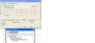
One more question. I’ve been setting up to use a MSG instruction to send/write to the Ultra 3000i and in the configuration window for the MSG instruction under "Communications -> Path. Does the node number of the Ultra 3000i follow after the 1756-DNB.

Example: Ultra_3000_Device_Net 10


Dnet.jpg
 
The path will be "Ultra_3000_Device_Net, 2, x" where x is the node number of the Ultra 3000i motion controller.

The name of the 1756-DNB gets you to that module, then "2" is the Port number to get you onto the DeviceNet, then "x" is the node number of the motion controller.
 
I have a question about the explicit messaging. Are all the explicit messages writes saved to nonvolatile memory?
 
Yes. From page 1-4 of the Ultra 3000 Devicenet reference manual:

If you write to a parameter using an Explicit Message, the parameter value will be saved as a working value and in nonvolatile memory. However, if you write to a parameter using an I/O message, you can specify whether the parameter value should be saved in nonvolatile memory or not. Therefore, if a parameter value has to be modified repeatedly, then you should use I/O messaging and not save the parameter value to nonvolatile memory because the nonvolatile memory has a limited number of writes.
 
I just got done reading a tech note 27084 it states that in firmware release 1.3 and higher of ultra writing explicit messages is possible without writing to NVMEM. Can someone please further explain to me how this works.
 

Similar Topics

After successfully communicating with the Allen Bradley Ultra 3000i 2098-DSD-010X-DN over DeviceNet via a 1769-SDN :) I preceded to configure the...
Replies
4
Views
8,170
My servo motor MPL-B330P-S is controlled by an Ultra 3000i. The problem is that the active position is always different from position command...
Replies
0
Views
1,185
Hi All, I having some problems setting up a new drive using Ultraware. The application is a simple bucket conveyor that indexes along each time...
Replies
2
Views
2,366
Why cant i communicate with drive. I have the cable that is in the manual i have checked my com port. I have the ultra software.
Replies
2
Views
1,892
I have two AB ultra 3000i servos (2098-DSD-020X/C) with a 3-wire null modem to the PC using Ultraware Version 1.80.0.0 in Tools->Recover...
Replies
4
Views
2,583
Back
Top Bottom