Documenting Inputs

Join Date
Apr 2002
Location
Just a bit northeast of nowhere
Posts
1,117
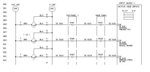
A while ago, we hashed about how to handle interposing relays on a schematics diagram. Now, I wanted to get some feedback on documenting inputs.

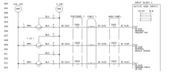
Below is how I handle it right now. A few specific things I'm looking for :

1. There is a 16-conductor cable running between the sub-panel and the main panel. The conductors are marked at both ends with the input numbers. How important is it to document the specific conductor number? What if the conductors are separated by colors instead of numbers? What if multiple cables are run between the same panels?

2. If the conductors should be specified (I'm leaning that direction), what is a good way to do so? In the past I used "C1-xx" designations, but this seemed to produce confusion.

Thanks!

TM
inputs 1.jpg
 
Last edited:
I think if you use one color you dont need to do nothing.
The way you document your wire it OK.
If you use separated color you can add the wire color or the wire No if you use multi cord cabel.

I also would suggest you to document the cabel or the pipes No to the sub paneles.
I dont think you should be specified the conductors by different No. Input or output No should be good enough.
 
cable sheet

i am alawyes generate a cable sheet .this cable sheet contains the source and destination of the cable,the cable no. in the project,each conductor number/color specifying in front of it it' :D s label in the source and destination.
 
cABLES

Tim,
Looking at you interconnect, someone troubleshooting this system could have a hard time determining whether the "cable" was actually a cable or individual strands of wire. Also, is this cable shielded? Which end does the shield wire (drain) terminate? Does the shield continue from point A to point B?
We usually try to indicate cable number on the interconnect and show that the interconnecting "wires" are in fact cables, and not individual runs of wire. You can do this several ways, but grouping the "wires" together (on your interconnect drawing) with a loop or circle, and, tagging the entire group C-1xxxx works fine. This also give you the oportunity to show the shield ire/drain wire pathway.

Now, as Heham said, we typically use a conduit/cable schedule to reference cable number, cable type (pltc, etc.) # of conductors, AWG #, etc. This could be as extensive as you want.
Hope this helps.
tj
 
What I do for multi-conductor cable is stick the color or number within parenthesis 'inline' on the schematic. It winds up looking something like this:

--------(BRN)------------

-or-

---------(2)-------------

In AutoCAD, I just type it as regular text justified to 'middle', then 'trim' the circuit line to the text. Using 'trim' gives you a nice, small gap on either side of the text.

Doing it 'inline' distinguishes it from a circuit number, etc.

beerchug

-Eric
 
I didnt have any problem with how it is
EXCEPT
Why is +24vdc AND 0(common) both numbered 505?

Does the octagon represent something besides a wire number?

1, 3 and 4 look like the wire numbers for the switch/prox
 
Last edited:
rsdoran said:
1, 3 and 4 look like the wire numbers for the switch/prox

I 'think' they represent the pin numbers of a quick-disconnect connector. If this is true Tim, I think the --<<-- should go closer to the switch, and the wire color indentification downstream of the connector. There are no (accessible) wires between the switch and the male connector, so identifying them in that location just leads to confusion (as Ron points out).

IOW, like I do it on MY drawings... ;)

beerchug

-Eric
 
Funny thing is I can follow it, I could use this to troubleshoot. The 24vdc and 0/common are identified, the switches are identified, the inputs are identified.

There are some details that may make it better or more precise but overall it would work.

I can not tell you HOW MANY machines I have dealt with that at every terminal strip connection a wire would change numbers. OR colored wire was used but they didnt seem to find it necessary to use color on the print, it used numbers. I think it took me awhile on that one to figure out the numbers and colors had a correlation and what it was.
 
rsdoran said:

Does the octagon represent something besides a wire number?


The octagon is the originating line number for the wires. He labeled the wire themselves as you mentioned.

This is a fairly common convention. I use arrows, though, to avoid confusion.

For a multi conductor cable, I would identify the conductor color or number in some way. I feel this is more important when one end of the wire is a connector of some sort and you can't put a wire number on each end.

I generally don't draw the pin symbols for a prox, I just put the conductor colors on the quick-disconnect cables right next to where they come out of the prox. The pin numbers won't be used because the connector is keyed, and it is pretty obvious that it is a connector to the person working on it.
 
Thanks!

Thanks for the feedback, guys! Looks like I'm on the right track, input-wise.

Eric / Ron :

The proxes are indeed quick-disconnect, but we actually assemble our own male plugs :) and I had quite a bit of trouble with cross-wiring those puppies back in the day. Thus, the color to the connector pin.

The octagons are indeed line jumps from the originating circuit, as Rick said. But we're gonna come back to that one soon, since it seems to be confusing people.

I think I like Taj's idea for a cable identifier, and Eric's idea for placing a wire number / color in-line. I'll make some adjustments and put up a new pic shortly.

In a related question, I like the idea of a cabling diagram very much. Could someone post an example of what one looks like, so I can see the kind of information involved?

Thanks!

TM
 
wiring specs

Tim,
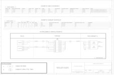
I am attaching a combo. cable schedule, conduit schedule, interconnect. Of course, they are usaully (3) sep. dwgs, but I put examples of what we use on (1) dwg to simplify. These are "process plant" oriented, but they may help. (By the way, I would post it in this message body, but I havnt figured out how to do yet?-any ideas?)
 

Similar Topics

Multiple PLCs in our plant communicate using either MSG instructions or Produce/Consume. Is there an industry best practice for documenting this...
Replies
3
Views
758
I've got an upload from an Omron SYSMAC CPM1A PLC but I cannot figure out for the life of me how to document the inputs and outputs. It's version...
Replies
9
Views
3,259
Hi there. I have a simple question with a lengthy post. How do you document projects (HMI or PLC programming) so that you or your coworker can...
Replies
12
Views
3,317
Dear, consultant is askign for a self documenting control system to provide hard copy for the record of configuration changes. However, the...
Replies
2
Views
1,357
Can anyone give me some quick tips on the best way to go about documenting a project in Concept? I've got a situation where the customer has lost...
Replies
4
Views
2,513
Back
Top Bottom